Dingle Memorial Tower: A study in conservation strategy development
By Paul Jeffs and Syd Dumaresq
For more than a century, the Dingle Memorial Tower overlooking the panoramic landscape of Halifax’s Northwest Arm has been a popular destination for not only the local community, but also countless visitors from beyond. In 1908, Sir Sandford Fleming donated to Haligonians the 38.5-ha (95-acre) Dingle Park, which gets its name from an Old English word meaning ‘wooded dell or valley.’ He proposed a monument should be erected there to commemorate the 150th anniversary of the first elected government in the British Empire (outside the Mother Country), which had taken place in Nova Scotia in 1758.1
Following a nationwide competition arranged by the Royal Architectural Institute of Canada (RAIC), a submission by Halifax-based architects Sydney P. Dumaresq and Andrew Cobb was selected. Strongly influenced by the Italianate style, the elegant 34-m (112-ft) stone tower included a copper-roofed viewing deck reached by a spiral staircase above three lower galleries.
The main body of the slightly tapered square tower was constructed using randomly dimensioned ironstone (i.e. sedimentary rock with substantial proportion of iron compound), while the viewing deck level and foundations are granite—both were quarried from nearby Purcell’s Cove. The interior walls are vertical, with the taper created by reducing the thickness of the walls from approximately 1 m (3 ft) at the bottom to 0.6 m (2 ft) at the tower’s top.
The viewing deck was designed with Palladian openings framed by Ionic columns; it was centred by decorative keystone arches on all four sides within ashlar-coursed granite walls. The massive ironstone body represents the millennia without elected government, while the highly finished granite viewing gallery represents the few years of the privilege of elected government. The interior walls of the galleries were adorned with various ornate plaques, shields, and crests (many fabricated from bronze or stone) donated by Canadian and overseas governments, authorities, and institutions. The stone plaques were cut from the native stone of the donors’ homeland. The tower opened to the public in 1912.
Deterioration mechanisms
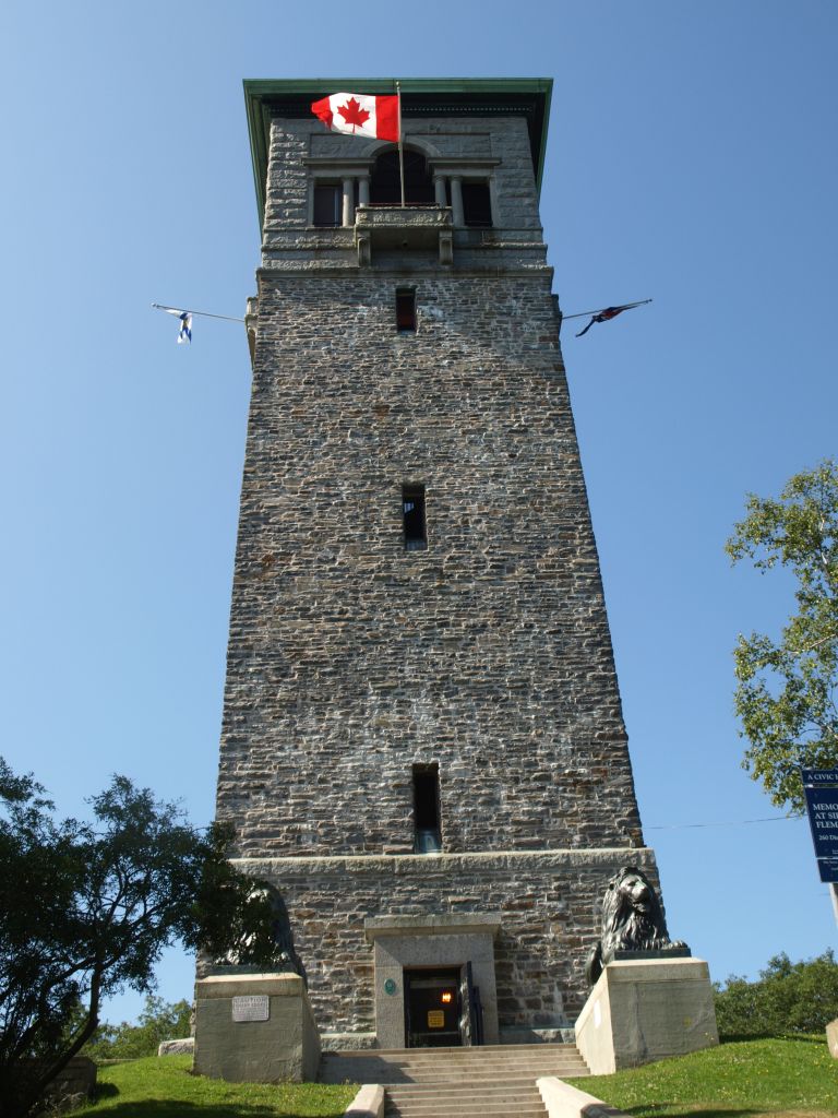
During the decades of exposure to a coastal environment that followed its construction, the tower’s masonry joints began to deteriorate, with vertical cracks propagating within both the exterior and interior wythes. Rainwater subsequently entered the cracks to saturate and deteriorate the lime mortar used to bind and joint the stone units within the wall assembly’s inner portions.
This considerable volume of water gravitated within the masonry, dissolving and leaching out the lime, and leaving saturated voids within the paths it created. The water eventually penetrated to the interior, running down the walls and plaques, depositing lime over all surfaces as the water slowly evaporated (Figure 1). The natural iron deposits within the ironstone units were also leached to the surface, leaving rust stains as the water evaporated and the iron oxidized.
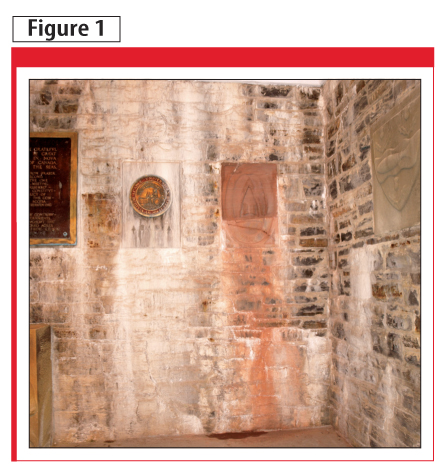
Extensive restoration work was carried out during the late 1990s and early 2000s, which predominantly included cutting out deteriorated masonry joints, applying bedding or repointing mortar, and carrying out masonry crack repair. Some concrete slab repair was also included and additional work was carried out to address corrosion of steel stairs and landings. However, within just a few years, many of the repaired cracks re-opened and new cracks began to propagate (Figure 2).
Pre-conservation project investigations and strategy development
By 2010, it had become evident further restoration work was urgently required; a Request for Proposal (RFP) was accordingly invited from architectural companies by Halifax Regional Municipality. This resulted in S.P. Dumaresq Architect Ltd., being retained. The firm then set about developing a scope of work and conservation plan, establishing a team of conservation experts, and providing prime consultant services for the overall restoration project.
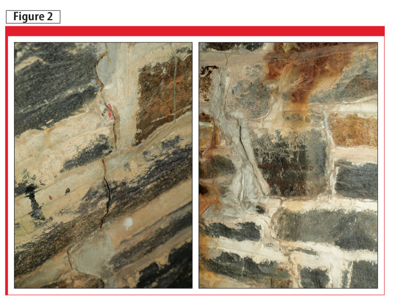
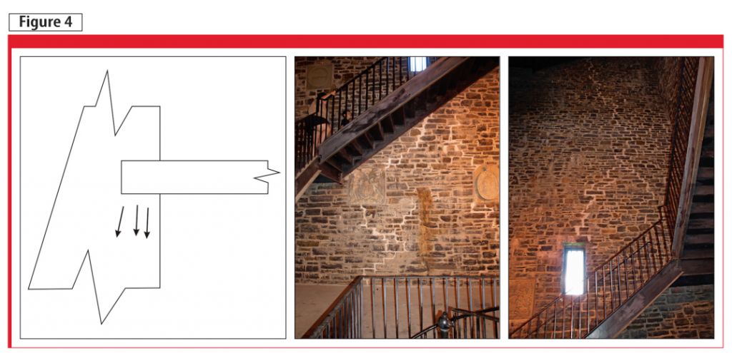
Preliminary investigations were first carried out to evaluate the most likely cause or causes of the extensive number of cracks, which—from their vertical orientation—had the appearance of being linked to an overload condition. After reviewing the available design details, comprehensive inspections were carried out from grade level, and from the various floor levels within the tower. From these, and a review of the tower masonry construction system, it became evident the perimeter edges of the intermediate floor slabs terminated on beams within the middle section of the masonry assembly (Figure 3).
It was determined the combined effect of the short projection of the floor slabs into the masonry and the fact that the walls tapered outward had resulted in gravity loads being concentrated within the inner wythe—hence the predominance of the cracking within the tower’s interior masonry (Figure 4).
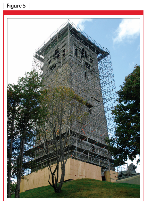
Since the tower was situated atop a knoll surrounded by woodland, it was not feasible to use a crane or telescopic lift equipment to access the upper levels of the exterior. Consequently, scaffolding was erected around the tower to facilitate close-up inspections of all four elevations, as well as to enable non-destructive testing and intrusive investigations (Figure 5).
After the investigation phase, the scaffolding was eventually handed over to the contractor who was awarded the restoration work. The additional rental costs for the scaffolding’s early installation was offset by the considerable convenience provided, not only for the consultants’ investigations and trials, but also for the bidders for the restoration who were able to closely examine the extent of the work before submitting their bids.
Primary investigations
Once the scaffolding provided full access to the tower’s exterior, investigations were carried out so a conservation strategy could be developed. This included:
- visual observations to further evaluate the condition of masonry at exterior upper levels not previously accessible;
- evaluation of masonry using ground-penetrating radar (GPR) to confirm the likelihood the inner core’s destabilization was a contributory cause of cracking;
- evaluating concrete slabs and beams with GPR to verify adequate structural capacity;
- creating a limited number of openings within the exterior and interior masonry so the nature of the masonry assembly construction could be confirmed and data provided by the GPR evaluations could be verified;
- drilling holes at selected locations to determine the type of equipment required based on practical difficulties encountered (and to confirm exterior masonry depth over the embedded concrete suspended floor slabs);
- evaluating potential for achieving adequate embedment and pull-out strength of stainless steel helical masonry ties to facilitate the development of a strategy to improve the masonry assembly’s composite action;
- evaluating potential for achieving adequate embedment and pull-out strength of mechanical anchors, so their installation could subsequently improve load transfer from the interior suspended slabs across the masonry assembly;
- evaluating grouting equipment, materials, and techniques to develop a strategy for injecting cellular foamed cement grout into voids hidden within the masonry assembly (and for determining a potential volume of grout for bidding purposes); and
- evaluating a low-pressure cleaning system using a mild abrasive medium to determine whether heavy deposits of leached lime could be effectively removed from masonry without causing damage to the substrate.
Visual observations
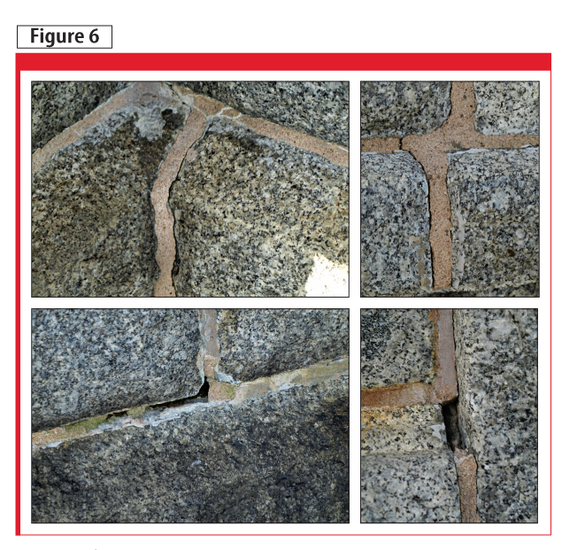
The close-up inspections were able to verify the masonry’s overall condition was—apart from the cracked sections and deteriorated joints—reasonably good; very little stone unit replacement work would be required. However, it was evident water could readily enter deteriorated joints, particularly between granite units within the viewing deck structure (Figure 6).
It was also apparent the mortar had not bonded well to the granite, particularly in view of the different co-efficients of thermal expansion and contraction characteristics of the two materials. Further, it was observed gravity loads were being concentrated at window openings—this no doubt contributed to cracking of lintels and adjacent masonry.
The information gained from the visual observations was used for the development of the conservation strategy and subsequent technical specifications.
Ground-penetrating radar evaluations
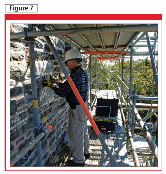
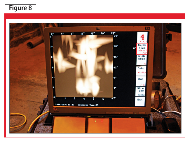
GPR is a non-destructive test method incorporating radar antennas that emit short, precisely timed pulses of radio frequency energy into the structure under test. The pulses are emitted from a scanning head when connected odometer wheels are moved over a temporary 600 x 600-mm (24 x 24-in) test grid at 100-mm (4-in) spacings on an X and Y axis (Figure 7).
Part of the energy subsequently echoes back to the surface to be analyzed by a computer, which records how ‘loud’ the signal is and how long it takes to return to the antenna. A software program analyses the raw data and generates the results and images (Figure 8). Eight locations of masonry were tested in this manner, both on the exterior and within the tower. The same equipment was also used to verify the presence of adequate embedded reinforcing steel.
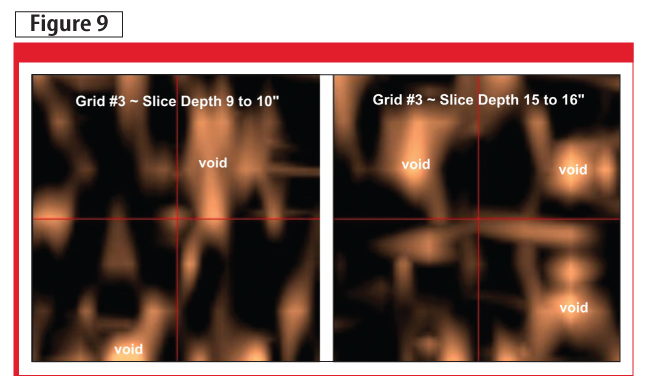
These GPR data confirmed the presence of a large number of voids at all depths within the masonry, and the degree and size of the voids considerably varied (Figure 9). There was little doubt these voids would have provided ‘reservoirs’ containing large volumes of infiltrated water within the masonry assembly, and they would continue to cause accelerated deterioration unless they were addressed by the restoration.
Openings
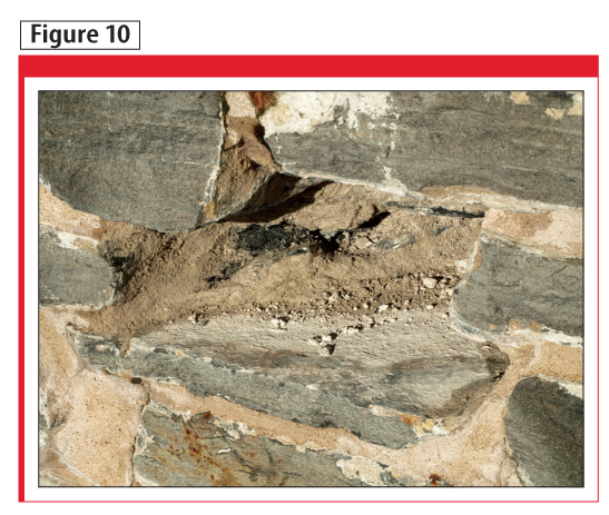
The temporary removal of several stones confirmed the assembly was not constructed to have walls containing traditional inner core rubble. The rough-hewn units had evidently been fabricated to produce random depths that varied considerably—up to about 350 mm (14 in.) within the openings made. These had been laid in random-course-height modules infilling completely across the masonry assembly.
This knowledge confirmed grouting would be difficult, since voids would not necessarily be completely interconnected for grouting purposes. It was also interesting to note several days after one of the openings had been made, water was still gravitating from above to maintain the mortar within the opening in a saturated condition (Figure 10). This further confirmed the importance of dealing with entrapped moisture within the restoration strategy under consideration at that time.
Drilling and tie/anchor investigations
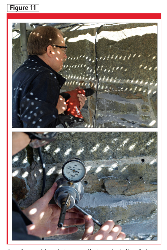
Both trial drilling and the installation of stainless steel helical masonry ties and mechanical anchors during the investigation stage provided valuable information that greatly assisted in the development of the conservation strategy and subsequent technical specifications (Figure 11). The drilling, installation, and testing were carried out by the materials and equipment supplier proposed to be used for the project.
Exploratory drilling confirmed the toughness of the ironstone required slightly larger pilot holes than would be normal for the installation of stainless steel helical ties. Not only were the standard diameter holes difficult to drill, but the ties were also unable to be installed satisfactorily, since they could not ‘bite’ into the stone for their full length. The trials also verified increasing the diameter facilitated adequate installations without overly compromising the development of pull-out load capacity. It was also determined sleeving the ties during installations prevented flexing that otherwise could result in bending.
Testing the ties and mechanical anchors verified excellent pull-out load bearing capacities could be achieved in both stone and mortar. This information was subsequently used to determine the optimal tie and anchor diameters, lengths, and spacings for inclusion in the specifications, as well as the equipment and techniques necessary to install the ties. Exploratory drilling established the locations from the exterior of the back face of the concrete beams supporting the interior slabs.
This information, together with estimated wall section thicknesses at the slab levels, subsequently facilitated the design of the length of mechanical anchors for inclusion in the specifications. The objective of installing mechanical anchors into the concrete beams was to transfer some load imposed by the floor slabs, reducing the potential for masonry re-cracking.
Grouting trials
The consultants recognized there were few companies (if any) in the region specializing in grouting of masonry similar to the tower assembly. Therefore, they developed a concept in which the pre-project trials would establish the equipment to be used, as well as the materials and other practical factors. A manufacturer of suitable equipment was therefore contacted to provide onsite training to a specialist contractor hired to carry out the trials.2 This formed the basis for the development of the specifications, which required the grouting companies bidding for the work to undergo similar training if awarded the project. Two areas were selected at the floor slab within the second level—one on the interior and one to correspond with the same location on the exterior.
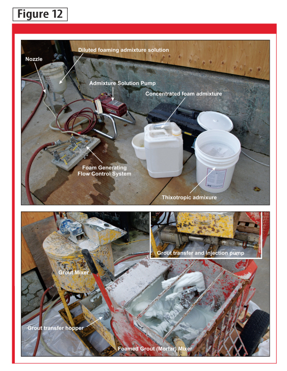
The equipment consisted of a high-speed cement grout mixer for mixing neat cement and water. A thixotropic admixture to provide grout gelling and cohesive properties was then added to the mix. The mixture was then transferred by pump to a conventional horizontal spiral blade mortar mixer. Foaming equipment was employed for the development of a cellular foam, which was then blended into the mixed cement grout (Figure 12). This combination was chosen because of the material’s lightweight and fluid properties (along with the small amount of water needed to produce the fluidity). Another important property was its low strength; weaker than the original masonry mortar, it served as a sacrificial replacement.
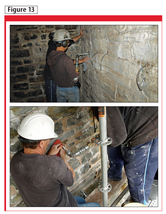
After adjustments of foam for the desired density range, cellular foam grout was transferred into the pump and injected into the masonry through tubes inserted into 300-mm (12-in) deep holes that had been pre-drilled at 600-mm (24-in) centres. (Figure 13).
The amount of grout injected through a known area/volume of masonry was calculated; it was used to assess the quantity of grout likely to be required. The estimate (adjusted for a waste factor) was then incorporated within the project’s bid form/specifications.
Cleaning/lime deposit removal
A system was selected for the cleaning trials that had a proven track-record for use on heritage masonry. Equipment was supplied and operated by Coastal Restoration & Masonry Ltd., it involves a low-pressure vortex process that uses a mixture of air, fine inert powder, and relatively small quantities of water. It has been deemed particularly effective for the removal of carbon, dirt, scale, micro-organisms, and all types of atmospheric pollution from brick, wood, and stone.
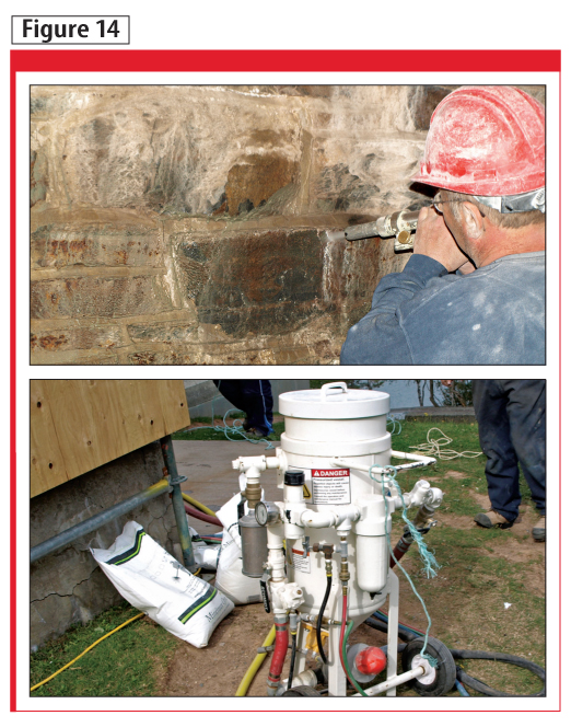
The lowest possible pressure range was selected, employing the mildest possible abrasive medium that could effectively remove the heavy lime deposits without causing damage to the underlying substrate (Figure 14). This information was required so specifications could effectively establish the requirements for this operation. The philosophy/objective was also to remove the deposits without trying to produce an ‘as-new’ level of cleanliness.
The trials verified a satisfactory cleaning process consisted of an operating pump pressure in the order of 0.2-kN (35-psi) using the finest grade of glass-bead abrasive medium. In fact, the next larger size of glass bead was found to be less effective since a higher percentage of rebound occurred, resulting in more material being required.
within the concrete ring beams and a high-strength grout was
injected at the beam locations.
Conservation strategy
The knowledge gained from the investigations and trials resulted in the development of the following strategy:
- The plaques were first protected by sealing them within wooden enclosures covered by a waterproofing membrane.
- Lime runs and other contamination were removed from the interior using the selected cleaning method. This was particularly necessary so mortar joints could be clearly visible during cutting-out operations that were to follow.
- All ironstone exterior mortar joints were cut out back by at least 25 mm (1 in.), but to sound mortar and back-pointed using a proprietary prepackaged hydraulic-lime-based bedding mortar. It was important this work was done in advance of the interior work, to prevent further ingress of moisture and permit the first stages of drying to begin.
- The interior ironstone joints were cut out back to sound mortar, deep pockets filled (plugged) with hydraulic lime mortar, and left open until the project’s last stage. This improved moisture vapour transmission to the tower interior, hastening the drying process.
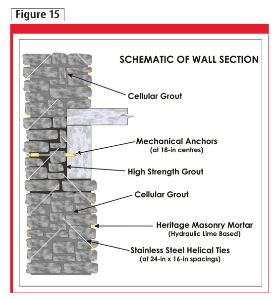
- Stainless steel helical masonry ties were installed from both the interior and the exterior to provide an improved composite action across the masonry assembly and provide restraint to pump pressures during the grouting operations which were to follow (Figure 15).
- Mechanical anchors were installed from the exterior to embed within the concrete ring beams and a high strength grout was injected at the beam locations. The objective of this operation was to transfer gravity loads from each floor slab across the entire masonry assembly (Figure 15).
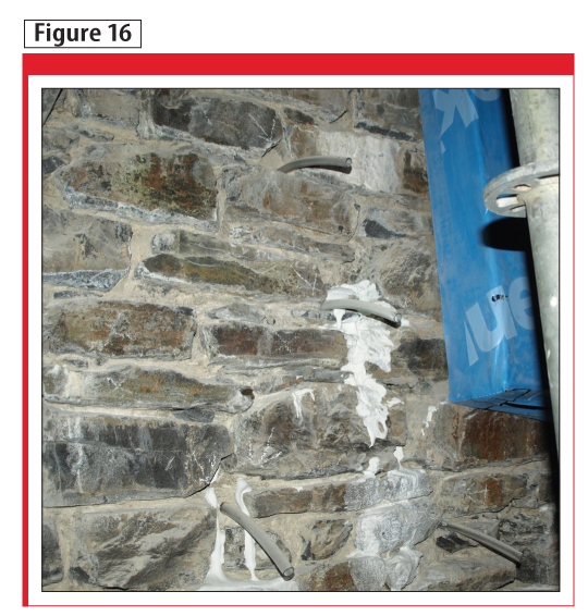
- Voids within the masonry assembly were then grouted from both the interior and exterior to fill as many remaining voids as possible using the cellular foam grout (Figure 15). Apart from the improved composite action provided by this operation, the voids were thereby prevented from providing ‘reservoirs’ of water within the assembly. At some locations, it was possible for grout injected from the exterior to penetrate full thickness of the masonry (Figure 16).
- Lengths of stainless steel helical reinforcing rods were installed into joints above and across window openings. This was to better transfer gravity loads away from the openings, thereby preventing the stress concentration that had previously adversely influenced cracking.
- The grout tubes were removed from the exterior, the surfaces cleaned to remove lime runs, and the ironstone joints face-pointed using the hydraulic lime mortar.
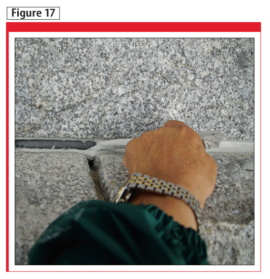
- The mortar within the granite masonry component joints was cut back, joint surfaces were cleaned, and a backing rod was installed. An elastomeric joint sealant was then installed within primed joints. Pre-installation trials confirmed a primer would be essential if adequate adhesion was to be achieved to the tough granite surfaces (Figure 17).
- Hot air was then introduced into the interior of the tower in an attempt to accelerate drying. Moisture sensors were installed at key locations to monitor the progress of the forced dehumidification operation. (Unfortunately, tight scheduling and costs prevented the drying from continuing to the point where no moisture remained within the masonry.)
- Finally, the interior joints were face-pointed and conservation work carried out to the commemorative plaques.
Conclusion
There were two important lessons to be learned from the conservation of Dingle Memorial Tower. First, a comprehensive investigation can sometimes be essential if the original cause of damage is to be identified and adequately addressed to prevent re-occurrence. Second, carrying out comprehensive trials of critical operations in advance of the development of technical specifications—rather than mockups immediately before the actual work—can provide valuable information. Without this data, inadequate procedures could be specified, leading to conflict and cost over-runs. Understanding the likely cost of the grouting operations was also a benefit when developing estimates for budgeting purposes.
Due to the presence of residual moisture remaining within the masonry assembly, some lime runs have re-occurred since the work was complete. However, the hope is the tower has now been restored to a durable condition, with its heritage value conserved for the enjoyment of future generations.
Notes
1 The authors would like to thank Halifax Regional Municipality (HRM) for its permission to publish information and photographs of Dingle Memorial Tower. The HRM project manager for the project was Lou Dursi. The restoration contractor was Coastal Restoration & Masonry Ltd (Goodwood, NS). (back to top)
2 The onsite training was provided by Multiurethanes Inc (Mississauga, Ont.). The grouting trials were carried out by Coastal Restoration & Masonry Ltd. (back to top)
 Paul Jeffs has more than 40 years of experience in the construction industry around the world. He is principal of PJ Materials Consultants Ltd., a Guelph, Ont.-based company that provides consulting services across Canada for the construction and restoration of masonry and concrete structures. Jeffs can be contacted via e-mail at pjeffs@pjmc.net.
 Sydney Dumaresq is a fourth-generation architect practising in Nova Scotia. The firm at the time of the Dingle project included his grandfather, Philip, the son of the Tower’s co-architect. Looking at his grandfather’s signed original drawings, with father and son collaborating on the conservation, was a pleasure and a privilege. He can be reached at syd@spda.ca.
Sign up for our weekly newsletter
Construction Canada weekly newsletters give the latest AEC industry news for those who build, design, engineer, specify, renovate or operate in the built environment.
Products & Services


Read the Latest Issue