Reducing energy consumption with continuous insulation
By Chris Norris, P.Eng, PE, LEED AP, Bryce Brandon, MBA, LEED GA, and Medgar Marceau, PE, ASHRAE, CSI, CDT, LCA CP, LEED AP
In both Canada and the United States, there is increasing awareness of the building envelope’s role in conserving energy. New energy codes and standards include prescriptive requirements for continuous insulation to minimize heat loss associated with thermal bridging.
South of the border, the 2009 International Energy Conservation Code (IECC) contains requirements for ‘continuous insulation’ installed on the wall’s exterior in six of eight climate zones. The Canadian approach in the upcoming edition of the Model National Energy Code of Canada for Buildings (MNECB), to be published in 2012, will stipulate an overall heat transfer coefficient (i.e. U-factor) based on the heating degree-days for a specific project location. Although continuous insulation will not be explicitly required, the advantages of using this strategy to meet U-factor requirements are myriad.
Requirements for air barrier systems have evolved differently in Canada and the United States. Canada has been a leader in the development of, and requirement for, these building components. The country’s focus has been on durability and meeting the twin National Building Code of Canada (NBC) objectives of health and safety. Air leaks can cause condensation and bulk water penetration in buildings, resulting in deterioration of building elements and compromising health and safety. Energy conservation has been the American focus for the requirement of airtight construction. In 2001, Massachusetts became the first state to incorporate a quantitative air barrier code requirement, with six others following suit. The reasoning in both countries is valid, while the approaches reflect the differences in national code development.
This article explores the findings of a study that evaluated the provision for ‘continuous insulation’ in wall design and the important effect played by airtight construction. The U.S. prescriptive requirement for ‘continuous insulation’ requires the exterior cladding be cantilevered out from the wall structure by the thickness of the insulation. This cantilevering of loads can present structural challenges resulting in increased structural costs. It can also be particularly challenging for retrofit projects where the original walls were not designed to accommodate these additional loads and where the structural supports themselves constitute considerable thermal bridges.
For the study, the relative benefits of exterior insulation and finish systems (EIFS) were evaluated—comparing performance based on American Society of Heating, Refrigerating, and Air-conditioning Engineers (ASHRAE) 90.1, Energy Standard for Buildings Except Low-rise Residential Buildings, compared to earlier versions as a baseline for evaluating the advantages of retrofit and new construction.
In CAN/ULC S716.1-11, Standard for Exterior Insulation and Finish Systems (EIFS)–Materials and Systems, Underwriters Laboratories of Canada defines the assembly as a:
non-load-bearing wall cladding system comprised of rigid thermal insulation board, an adhesive for attachment of the thermal insulation board to the substrate or water resistive barrier system, a glass fibre reinforcing mesh embedded in a base coat on the face of the thermal insulation board, and a finish coat.
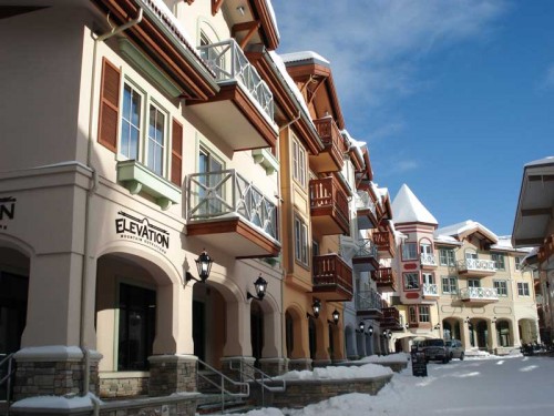
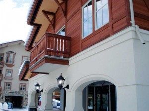
The new standard applies only to EIFS “used in combination with a drained air space and liquid-applied water-resistive barrier (LA-WRB), as an exterior wall cladding system.” EIFS has been used effectively as an insulated cladding in Europe and North America for more than 30 years.
Energy modelling objectives
The objective of a recent energy modelling project was to evaluate the relative benefits of two continuous insulation EIFS systems—one with an air barrier, one without—for new construction and energy retrofit applications.
A prototype medium three-storey office building was modelled for three climates: Dallas, Texas, Seattle, Wash., and Toronto. Various scenarios for retrofitting existing buildings and for design upgrades for new construction were considered. The baseline case buildings were modelled as meeting the minimum requirements of ASHRAE 90.1-2004 for existing buildings and ASHRAE 90.1-2007 for new buildings. (Some of the prescriptive requirements in Canada’s MNECB are based on ASHRAE 90.1.) A baseline air leakage rate of 7.9 L/s•m2 (1.55 cfm/sf) of above-grade envelope surface normalized to 1.57 psf (75 Pa) was used. (For more information, see the 2009 ASHRAE Handbook of Fundamentals).
Existing building baseline and retrofit
The baseline existing building was:
- 5000-m2 (53,600-sf) three-storey building meeting minimum prescriptive requirements in ASHRAE 90.1-2004;
- batt insulation in stud space for Seattle and Dallas, and continuous insulation for Toronto climate per requirements in ASHRAE 90.1 based on climate zone;
- 33 per cent glazing: solar heat gain co-efficient (SHGC) was as follows:- Dallas–0.25;
– Seattle–0.39; and
– Toronto–0.39;
- U-factor for all three cities was 3.24 W/m2 K (0.57 Btu/h•sf•deg F);
- air leakage rate: 7.9 L/s•m2 (1.55 cfm/sf) envelope area at 75 Pa (1.57 psf) pressure difference normalized to 4 Pa (0.08 psf); and
- steel-stud-framed exterior walls with brick veneer.
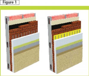
Two retrofit cases were considered for each climate zone. For the first, a 50-mm (2-in.) thick barrier EIFS assembly, without an air barrier, was added to the baseline model without changing the building air leakage rate. For the other case, a 50-mm EIFS assembly with an air barrier was included, with the air leakage rate reduced to 2.0 L/s•m2 (0.4 cfm/sf) at 75 Pa (1.57 psf) pressure difference normalized to 4 Pa (0.08 psf). See Figure 1.

New building baseline and energy design upgrade
The baseline existing building was:
- 5000-m2 (53,600-sf) three-storey building meeting minimum ASHRAE 90.1-2007 requirements;
- batt insulation in stud space and continuous insulation (minimum code compliance level of insulation);
- 33 per cent glazing: SHGC used was the same as existing building baseline;
U-factors were:
-Dallas–3.41 W/m2 K (0.60 Btu/h•sf•deg F);
-Seattle–2.84 W/m2 K (0.5 Btu/h•sf•deg F); and
-Toronto–2.56 W/m2 K (0.45 Btu/h•sf•deg F); and
- air leakage rate: 7.9 L/s•m2 (1.55 cfm/sf) envelope area at 75 Pa (1.57 psf) pressure difference normalized to 4 Pa (0.08 psf).
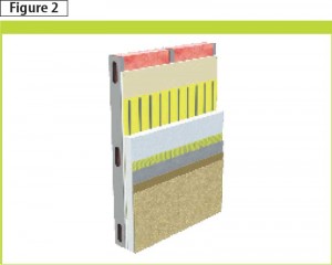
The energy design upgrade cases replace brick with the air barrier/EIFS combination (Figure 2). In upgraded cases, the air leakage rate was reduced to 2.0 L/s•m2 (0.4 cfm/sf) or 1.3 L/s•m2 (0.25 cfm/sf) depending on the scenario. The thickness of the exterior EIFS was varied from prescriptive minimum up to a maximum of 250 mm (10 in.).
Sign up for our weekly newsletter
Construction Canada weekly newsletters give the latest AEC industry news for those who build, design, engineer, specify, renovate or operate in the built environment.
Products & Services


Read the Latest Issue