Facing The Changes: Rainscreen drainage planes versus furring strips
By John Koester and Mark A. Johnson
“Change is the law of life,” John F. Kennedy once said, “And those who look only to the past or the present are certain to miss the future.” This idea ‘change’ is irrefutable has been proven true countless times. Within just the last few years, technology has forever altered the way those in the design/construction realm work, to say nothing of the way we live. Still, many are slow to embrace the idea of change, with many of us actually dreading it.
The building envelope sector, for example, seems to embrace the status quo with exceptional tenacity. There are obvious reasons for this unwillingness; product manufacturers do not want to see change unless they have another material that fits with the new way of doing things. Also, many tradespeople do not want to learn new techniques when current practice has served them well for so long.
There is a long list of players who could be negatively impacted by the implementation of new technologies, materials, and techniques, including:
- the shipping and storage industry;
- unions;
- contractors;
- raw materials producers;
- architects;
- specifiers; and
- code officials.
Building is a complex process, and there are countless individuals and organizations involved.
Images courtesy TMI
It is unfortunate ‘change’ is often preceded by the words, ‘forced to’—mandates do not always engender quality. One of the more common forms of force used to change the construction industry is through codes. These require the building industry to conform to a ‘minimum standard’—essentially, the very least one can do without breaking the law and being subjected to fines and/or imprisonment.
Economics is the other factor that brings about change. If a product is cheaper, smarter, and sexier, and if consumers become aware of it, it will be demanded. Industry will also shift to new technologies if it sees an economic and/or marketing benefit. For example, how many products have suddenly become ‘green?’
This article focuses on the adoption of modern rainscreen drainage technologies by the construction industry as a solution to the entrapped moisture problem. The issue was first addressed in Canada in the last part of the 20th century because widespread failures of the exterior building envelope were occurring. Building scientists discovered a space between the backside of the veneer and the front of the backup wall could alleviate the problem, and the code was written to force this change.
In 2005, the National Building Code of Canada (NBC) was modified to include Subsection 9.27.2.2(b), “Minimum Protection from Precipitation Ingress.” This subsection states:
an open drainage material, not less than 10 mm [0.4 in.] thick and with a cross-sectional area that is not less than 80% open, is installed between cladding and the backing, over the full height and width of the wall.
Furring strip drainage systems
Contractors began using wood furring strips to create this space to allow moisture to drain down and out the building envelope, as well as to equalize air pressure between the front and the back of the rainscreen building envelope. As time passed, new materials—plastic, metal, etc.—began to replace the wood.
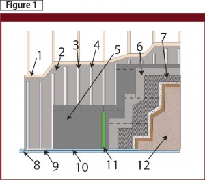
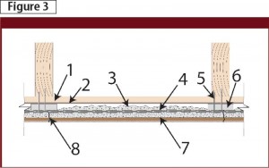
In most furring strip applications, additional materials are required to complete and support the construction of this rainscreen drainage plane detail. These include some type of semi-rigid moisture-resistant panel or roll-stock material used in combination with construction paper as a slip-sheet. A rainscreen drainage system created with furring strips (Figure 1) commonly comprises:
- sheathing (1);
- building paper (2);
- main furring that aligns with studs (3);
- intermediate furring (4);
- three-ply semi-rigid asphalt board (5);
- building paper—slip sheet (6);
- stucco lath (7);
- metal drip flashing (8);
- ventilation openings covered with screen (9);
- metal stucco stop (10);
- taped vertical joint of asphalt board (11); and
- three-course stucco (12).
There are several inherent problems with this type of rainscreen drainage system. The two that are probably the most negative are:
- too many components (i.e. a cost issue); and
- too labour-intensive (i.e. cost, time, and complexity issues).
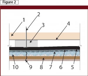
Another factor that negatively impacts this system is its violation of the most basic principle of moisture management—it fails to provide a means for moisture to effectively exit the building envelope (Figure 2). In Subsection 9.27.2.3(b), the 2005 NBC states:
the second plane of protection shall be designed and constructed to (see Subsection 9.27.3.1) (i) intercept all rain and snow that gets past the first plane of protection, and (ii) effectively dissipate any rain or snow to the exterior.
 For projects located in the United States, Section 703.1.1 of the International Residential Building Code (IRC) and Section 1403.2 of the International Building Code (IBC) affirm this point.
The three required components of a well-designed system to stop moisture penetration include:
- moisture-resistant materials (i.e. flashings, coatings, and weather-resistant barriers [WRBs]);
- slope-to-drain to direct moisture out of the construction detail; and
- predictable open channels (i.e. pathway to the exterior of the building/building details that allow moisture an unobstructed pathway out of the construction detail).
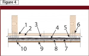
The furring strip rainscreen drainage system pictured in Figures 1 and 2 interrupts moisture at the building paper slip-sheet surface installed in front of the semi-rigid asphalt board. However, it does not provide a designed detail for this obstructed moisture to drain to the exterior. Figure 2 depicts the following:
- sheathing (1);
- fastener (2);
- intermediate furring (3);
- building paper (4);
- three-ply semi-rigid asphalt board (5);
- building paper—slip sheet (6);
- stucco lath (7);
- three-course stucco (8);
- stucco cracking (9); and
- moisture (10).
The waterproofing issue
The required drainage that must be provided in front of a moisture ‘water stop’ has a long history of being misunderstood and is often improperly detailed or even omitted in the design and construction of the exterior building envelope. The root cause of this problem may be the construction industry’s unrealistic comfort level with the idea of ‘waterproofing.’
The reason for waterproofing’s preeminence can be at least partially explained by the petrochemical industry’s rapid growth resulting in large volumes of byproducts in need of disposal. Examples include coal tar pitch from the coking of coal, along with asphalt from the distillation of petroleum. When these byproducts were found to be excellent waterproofing materials, a market was needed—enter the construction industry.
Before this period (i.e. about 125 years ago), various types of metals (e.g. copper and lead), some tree pitches, and animal fat-impregnated fabrics were the only moisture-resistant materials available. The construction industry’s only real moisture control was slope-to-drain. Slabs and boards of semi-moisture-resistant material were installed shingle-fashion on roofs with high pitches; they were also vertically installed on walls.
Coal tar pitch and asphalt changed all that and led to developments like low-slope and flat roofs. The petrochemical industry modified and improved on these original materials and also added many high-quality synthetic waterproofing materials. These abundant materials distracted the construction industry’s attention away from the necessity for drainage.
Dire need for drainage
With the avalanche of building envelope failures over the last two or three decades, the need for drainage in the building envelope moisture control equation has become increasingly clear. Furring strips were an early answer and served, at least for a time, as an imperfect solution. However, the early placement of furring strips created a new problem—the drainage plane in Figure 3.
Attached at each stud location, the strips pushed against the scratch coat of mortar, bellying it out and allowing the furring strip to come in close proximity to the stucco lath. This created a much thinner layer of stucco at each furring strip and often led to stress cracks in the three-course stucco—as shown by the (8) in Figure 3.
In an attempt to improve this application, an additional furring strip was installed midway between the 406 mm (16 in.) on-centre (oc) furring strips, as illustrated by (3) in Figure 4. This additional layer of furring strips alleviated some of the bellying/cracking problem, but it also created a new issue. The labour forces would occasionally fasten the expanded metal lath to this nonstructural termination (i.e. the intermediary furring strip), which led to more cracking.
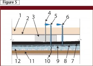
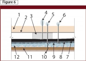
Excessive, uncontrolled cracking in the exterior building envelope rainscreen is unsightly, and it creates an opportunity for excessive moisture to ingress into the rainscreen and potentially deeper into the exterior building envelope. To make matters worse, the cracks were occurring at fastening points. This potentially allowed moisture a direct pathway along fastener shanks and into the stud cavity, as shown in (5) and (6) in Figure 5. This is the direct result of site workers incorrectly using nonstructural details as attachment points.
Incorrect placement of fasteners that penetrate to the backside of the backup wall sheathing and on through to the backside of roof sheathing causes real ‘leak’ issues. However, the moisture patterns seen on the backside of the sheathing may not be from ingressing moisture. Instead, they could be a water pattern caused by the melting of frost balls or condensation runoff.
The shanks of the misplaced fasteners may not be only pathways for liquid moisture, rather, they can also be pathways for cold temperature. The result is the points of the misplaced fasteners are cold enough to create dewpoints that, in turn, allow for condensation in the form of frost balls or water droplets (as shown in [4], [5],
and [6] in Figure 6).
Emerging methods
One new method attempting to improve the rainscreen drainage detail is the use of ‘mat’ materials. Most of these products come in the form of roll stock, and are created with various manufacturing procedures and materials. While different companies have proprietary differences, the primary examples are:
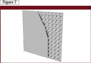
- continuous vacuum moulding of different types of plastic sheet roll stock material, creating a variety of shapes or raised patterns and dimples in the material (a second manufacturing process involves adhering a synthetic fabric to the tops of the raised pattern, as shown in Figure 7);
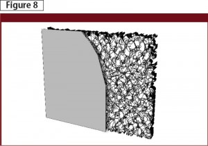
- the extruding of various types of plastics into filaments into various dimensions, then compressing and organizing them into continuous mats of a range of thicknesses and widths (a second manufacturing process involves adhering a synthetic fabric to one or both sides of this entangled filament mat, as shown in Figure 8);
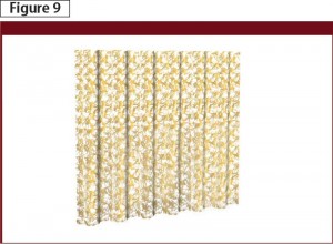
- the extruding of plastics into filaments of different dimensions and compressing them into a sheet that is then formed into different corrugated patterns (Figure 9); and
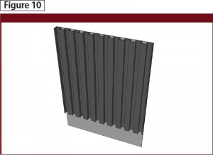
- the forming and perforation of a plastic roll stock material into a variety of corrugated patterns and thicknesses (a second manufacturing process adheres a synthetic fabric to one side, as shown in Figure 10).
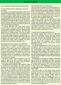
These four manufacturing procedures are used to create six of the major product lines that represent the mat rainscreen drainage plane technology in North America. (For more information, see “Product Choices” above.) They differ from one another in drainage efficiency, compressive strength, and ease of installation.
What they all bring to the construction industry, and specifically to the exterior building envelope segment, is ease of installation and in most cases, a more predictable cost-effective rainscreen drainage plane. When choosing which one of these new rainscreen drainage plane technologies to use in a project, it is critical to select the one that best suits the veneer/rainscreen type, and possesses a Canadian Construction Materials Centre (CCMC) evaluation number.
John Koester is founder and CEO of Masonry Technology Inc. (MTI). With construction experience dating back almost 40 years, he has been a card-carrying mason and cement finisher, and for many years operated his own masonry construction business in Minnesota. Koester has extensive background in waterproofing systems in the areas of forensics, design, and installation oversight—both in restoration and complete re-roofing projects. He can be contacted via e-mail at john@mtidry.com.
Mark A. Johnson began his association with the construction industry at the age of 16, working for several contractors in various roles throughout his high school and college years. Mark has been MTI’s media technologies manager for the past five years. His responsibilities include the design and management of MTI’s Web communications, their educational and training programs, and all digital marketing efforts. He can be reached at mark@mtidry.com.
Sign up for our weekly newsletter
Construction Canada weekly newsletters give the latest AEC industry news for those who build, design, engineer, specify, renovate or operate in the built environment.
Products & Services


Read the Latest Issue