Using ground-penetrating radar with concrete
By Bruno Silla and Roger Roberts
Many Canadian bridges have been deteriorating for decades or repaired and re-repaired throughout the years. How do the responsible authorities prioritize which concrete infrastructure needs to be fixed or strengthened and which needs to be outright replaced? How do they know which can wait until next year or formulate appropriate budgets? The answers lie in understanding and selecting the right combination of inspection and testing tools, including ground-penetrating radar (GPR).
As an example of non-destructive testing (NDT) that evaluates material properties without causing damage, this type of radar is used for detecting deterioration in bridge decks, but it can also assess the quality and uniformity of an asphalt or concrete highway surface. GPR can be ideal not only for gauging the stability and performance of concrete structures, but also for ‘seeing’ through materials before invasive work could otherwise adversely affect embedded wiring or cables. This article examines different GOR applications to provide design/construction professionals with a greater understanding of the technology and its use.
Ground-penetrating radar can be used on rock, soil, ice, fresh water, pavements, and structures—concrete or otherwise. (It is less effective on some very electrically conductive media, such as saltwater and most clays.) It employs radar pulses to create an image of the subsurface; GPR essentially uses electromagnetic radiation in the microwave band of the radio spectrum (i.e. UHF/VHF frequencies), and detects the reflected signals from subsurface structures to ascertain ‘hidden’ objects, changes in material, and voids and cracks.
The two most common types of GPR for bridge surface measurement are air-launched and ground-coupled. The latter relies on an antenna placed very close to the roadway/surface, while the former uses directional antennas aimed at the surface from a height of 305 to 508 mm (12 to 20 in.). Ground-coupled antennas have a reputation of being less prone to radio frequency interference (RFI) from cell towers and TV broadcasting, but typically operate at very slow speeds below normal highway limits. Air-launched antennas, even when travelling at 105 km/h (65 mph), are located at a safe height above the roadway surface.
Using GPR for bridge inspection
In comparison with other techniques (see “Sleuthing a Bridge’s Structural Success,” page 4), GPR technology can be quite advantageous for bridge inspection. The method is particularly well-suited to prioritizing for budgeting purposes. Further, while acoustical methods, for example, are very subjective, GPR data is quantitative.
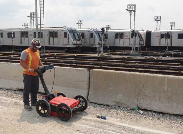
Typically, a cart-based system (including an antenna and a controller) is used, in which data is collected at a walking pace (or a vehicle travelling at about 8 km/h [5 mph]). The radar technology looks for weakness in the returning signal from the reinforcing steel—the weaker the signal, the more deteriorated the concrete. The technology can show the location and depth of rebar, tie bars, and dowel bars, as explored later in this article.
As mentioned, condition assessment can be performed using both air-launched horn antennas and ground-coupled antennas. The latter option provides better horizontal resolution—enough to enable imaging of individual reinforcement bars in the top mat, which is typically not possible with horn antennas. Ground-coupled antennas are used to collect densely spaced measurements along lines that are oriented so they cross over the top rebar in the upper mat at right angles (or close to a right angle if the rebars are skewed). The amplitude of the radar wave reflection from each rebar is recorded versus its location on the bridge. Relative changes in the rebar reflection amplitudes are typically indicative of the condition of the rebar and/or concrete above.
For maximum accuracy, rebar reflections arriving from reinforcement positioned at different depths may need to be corrected depending on the depth difference. This can be tricky as variation in concrete moisture can lead to the illusion of depth variation. Further, there are rules of thumb when picking the relative change in rebar reflection indicative of deterioration that requires maintenance. Often, the GPR practitioner will map surface defects and the corrosion evident from staining on the underside of the bridge deck to help fine-tune the deterioration threshold value.
New construction uses
GPR can also be used for quality assurance/quality control (QA/QC) of a new bridge deck, measuring whether the depth of the rebar meets the proper specifications. Concrete cover measurements are most often done during QA of the bridge deck after it has been poured to ensure the top rebar mat is at the depth range specified in the bridge plans. The measurements involve collecting data with a ground-coupled antenna along one or more profile lines to record the arrival time of the rebar reflections. Then, a core is drilled at one of the rebar locations to measure the rebar depth. This is input into the processing software, which calculates the radar wave velocity that is in turn used to obtain the depths of the rebar at other locations along the data-collection profile line.
This is a straightforward procedure providing very accurate rebar depths. The user should pick a rebar near the beginning or end of the profile line for the calibration core to ensure its depth can be matched up with the same rebar that generated the reflection detected in the GPR data.

