Maintaining Balance: The form and function of balanced door systems
By Mark Graves
Despite the fact doors are the first thing seen when entering a building, they are often the last thing thought about. An essential part of every building, these openings are frequently dismissed as a very small part of the overall project. However, doors are much more than that—they provide form, function, performance, and esthetics.
Entrances are usually the main focal point of a building’s exterior and become the centre of attention. Over the last century, door design and fabrication has evolved and diversified to meet a wide variety of esthetics and functions. Walking along a city street, one finds various door styles—such as hinged, pivot, or revolving—made of various types of metal, glass, and wood materials.
A style of door that has been around for more than 80 years is
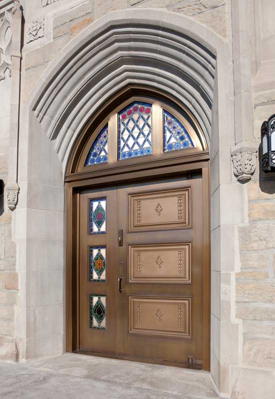
the balanced door. Since its invention in 1927, this assembly has graced the entrances of well-known museums, libraries, government facilities, flagship retail entrances, and corporate headquarters. From the Art Institute of Chicago and the Smithsonian buildings of Washington, D.C., to the Canadian Space Agency headquarters in Saint-Hubert, Qué., balanced doors have been specified for high-profile projects thanks to their customization and hardware allowing large, heavy doors to be opened with ease.
The door, frame, and balanced hardware create the complete assembly. The anatomy of a balanced door has been crafted to produce a ‘marquee’ entry system.
Anatomy
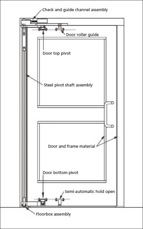
For a better understanding of a balanced door system, it is important to analyze each component. Balanced-entry systems may esthetically appear similar, but some parts are specific to individual manufacturers.
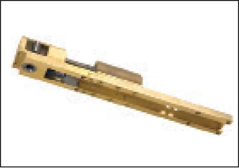
Check- and door-guide assembly
This assembly is located in the frame header above the door. A pivot shaft connects to the fixed end while the other hydraulic half is removable for necessary servicing without having to take out the door leaf. The assembly contains two valves to adjust the closing speed of the door—the initial closing speed and a second for the latching. Each valve can be independently adjusted from the underside. The assembly has a channel for the door-roller guide to move along when the door is in use.
Door-roller guide
The door-roller guide serves as the fulcrum, or pivot point, of the door leaf. It rolls along a channel located on the underside of the door-guide assembly as it opens and closes. Since this part takes a shock with each operation, the housing is made of a durable material—such as cast manganese—and a sealed, treated bearing steel roller.
Top arm
The top arm is one of the two connections between the door leaf and frame. A 25-mm (1-in.) stainless steel pivot pin connects one end of the top arm to the door top pivot. The other end is welded to a full-height steel-tube pivot shaft.
Door-top pivot bearing
Located on the top rail of the door leaf, a steel bearing accepts the 25-mm steel pivot pin to connect the door leaf to the top arm. The pivot bearing is adjustable to ensure proper door clearances.
Bottom arm
The second connection between the door leaf and frame, the bottom arm is thicker than its top counterpart because it carries the door’s weight. A 25-mm stainless steel pivot pin connects one end of the bottom arm to the door-bottom pivot. The other end is welded to a full-height steel-tube pivot shaft using four penetration welds to provide superior strength. Inside the bottom arm is a non-corrosive and self-lubricating bearing—one of the few plastic-type parts in the entire door system. Using plastic instead of stainless steel bearings provides long-term performance against water, salt, and other corrosives that may penetrate into the area.
Door-bottom pivot bearing
At the door bottom rail, a bearing accepts the 25-mm steel pivot pin that connects the door leaf to the bottom arm.
Steel-tube pivot shaft
The steel-tube pivot shaft houses the torsion bar closer spring. It runs the door’s height; one end of the top and bottom arms is welded to this shaft.
Torsion-bar closer spring
Located within the steel-tube pivot shaft, the torsion-bar closer spring provides the closing force for the door—and is fully adjustable to meet the required closing pressure. The top of the bar remains stationary while turning at the bottom (on the floor box) for tension adjustments. A torsion bar is superior to a traditional coil spring for durability. The heavy-duty design allows the use of heavy doors and frequent operation. Some manufacturers use a traditional coil-style spring for this part. Over time, this spring eventually weakens, loses tension, and stops proper functioning.
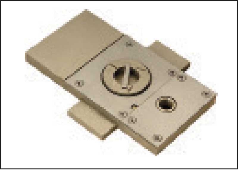
Floor box
The floor box is a base plate to accept the pivot shaft assembly. The door’s weight is distributed from the bottom arm to the floor box and ultimately down to the floor itself—eliminating the weight of the leaf on the frame as with traditional hinged doors. The floor box permits adjustment of the door closing force via the torsion bar closer spring with a 13-mm (1/2-in.) hex key. Each time the key is turned, it moves internal gears that torque the spring until reaching the desired tension.
Sign up for our weekly newsletter
Construction Canada weekly newsletters give the latest AEC industry news for those who build, design, engineer, specify, renovate or operate in the built environment.
Products & Services


Read the Latest Issue