
By Neb Erakovic, M.A.Sc., P.Eng., and Walter Koppelaar
With its iconic crescent-shaped, inversely curved form, the Bow is a striking presence on Calgary’s skyline. Designed by Foster + Partners of London, this 59-storey tower features a vast atrium partitioned in four clear-height sectors with the façade integrating an architectural exposed diagonal grid structure in six-storey segments. The perimeter ‘diagrid’ frame helps make up the building’s hybrid lateral force-resisting system (LFRS).
The Bow Tower serves as the new headquarters for Canadian energy corporations. The site includes two city blocks in downtown Calgary’s central area. At 238 m (780 ft), it is the tallest building in western Canada, and the second tallest commercial office in the country. The tower’s gross constructed above-grade area is 195,000 m2 (2.1 million sf), along with 97,000 m2 (1 million sf) at six below-grade levels, including 1375 parking spaces and loading dock and service areas.
All project team members successfully fulfilled roles in addressing unique design and constructability challenges, including the long-span structures’ irregular floor plates and sophisticated lateral system, along with delivering the fast-track project in a dense urban centre under harsh climatic conditions.
Other significant construction factors included the analysis and design of a temporary structure required during construction, superelevation and elastic column shortening, extremely tight erection tolerances, and a high standard of quality for the 8000-tonne architecturally exposed structural steel (AESS) atrium.
This article revisits the development of concepts, specifically design and construction details of the perimeter diagonal grid and the lateral system. It explores the logistics in the context of a ‘top-down’ construction technique for the substructure employed to accelerate the schedule. It also examines the above-grade tower superstructure, which is characterized with large and heavy building components and reflected in the fabricator’s perspective on production and erection of complex AESS elements to tight tolerances, along with a fast-track construction schedule. (The authors would like to thank H&R REIT, the tenant, Ledcor Construction, Matthews Developments Alberta, Foster + Partners and Zeidler Partnership, Supreme-Walters Joint Venture, Yolles–A CH2M HILL Company, Barry Charnish, and David Stevenson, and everyone else who contributed to the success of this project).
Architectural concepts
The Bow successfully fulfils its owners’ goals of a distinctive tower that is both a progressive and sustainable office space and a vibrant cultural, civic, and shopping destination for Calgarians. Three ‘sky gardens’ divide the building into distinct zones, forming a series of destination floors with lobby areas, meeting rooms, communal spaces, and a high-speed lift service running between the lobbies.
Early design meetings with the client identified the prime objectives for the development. These included a distinctive image, a ‘home-away-from-home’ ambiance, a desire to transform the local area in downtown Calgary and tie into the enclosed pedestrian path though the downtown buildings, and a way to introduce landscaping at the base to facilitate interaction with the public.
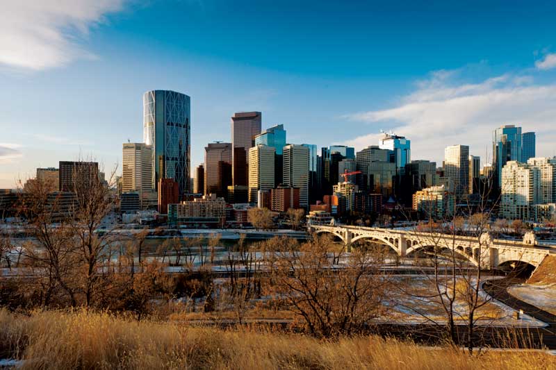
An assessment of the space planning and business units became the basis for the building’s architectural design. Foster + Partners explored various floor plate configuration and layouts for consideration by the client; each was studied for building efficiencies, functionality, economics and esthetics. Figure 1 (left) illustrates the final contestants in the design process, along with options for the building’s vertical profile.
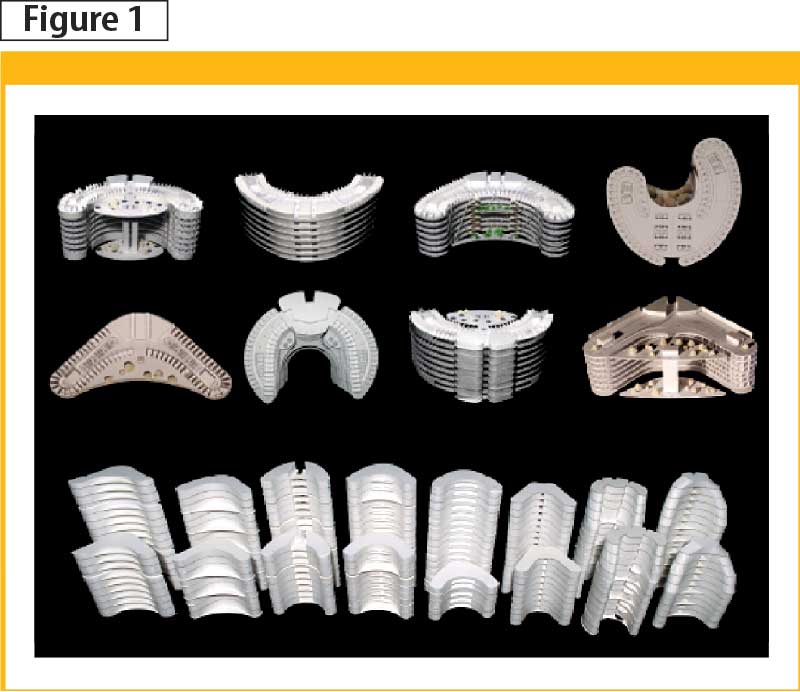
As a result of the client’s office culture, there was a significant requirement for perimeter offices for their staff—as opposed to the recent trends in office layouts with ‘seas’ of office cubicles or systems furniture. Conversely, interior areas were needed to provide meeting rooms and support facilities. The most typical office floor is shown in Figure 2, with the elevator banks in a side-core position clustered with the washrooms and the north-facing stairs. The shape selected also had the benefit of minimizing the length of the perimeter and interior wall system surrounding the atrium area, and capitalizing on the view of the Rocky Mountains on the south.
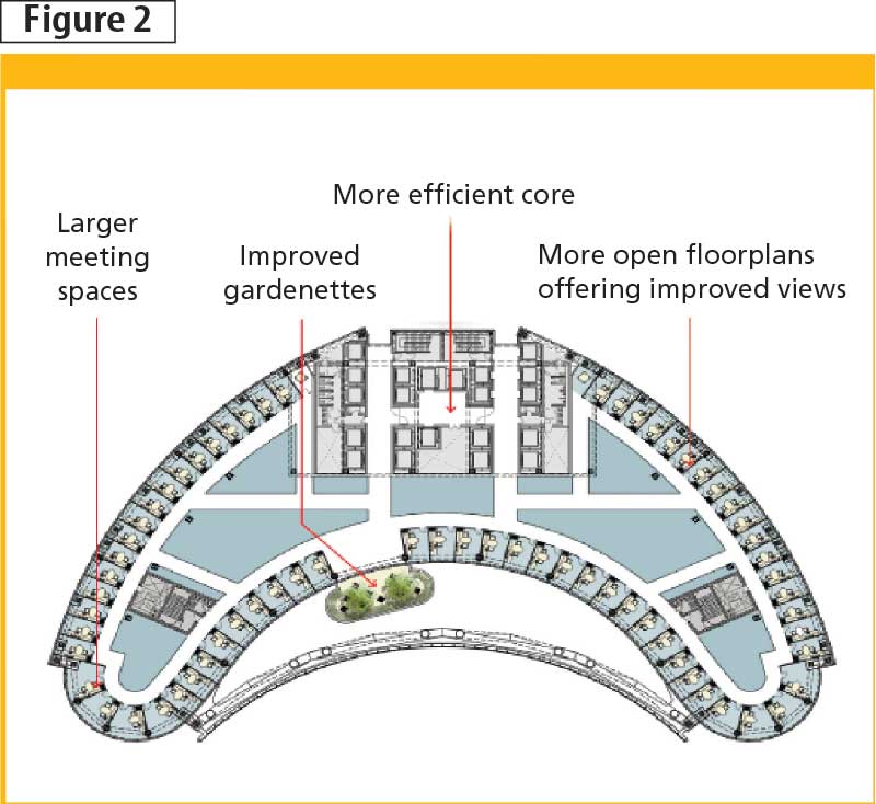
The tower’s shape is more than a visual statement—it also helps with the pursuit of sustainable design goals. The curving bow shape meant wind loads were reduced when compared to a rectangular building. This improved the economies of the building, resulting in effective building material use. Studies were carried out to position the building to maximize sunlight to the office space and to internal gathering locations; the findings partially helped determine the crescent-like shape, with the interior curvature facing to the southwest (Figure 3).
Using this interior curvature captures sunlight; the shape also gave rise to the locations of the atrium along the southwest elevation. This atrium or plenum-type buffer zone is designed to absorb the heat from daily sunlight and use it to partially warm the building in the winter; it also buffers the solar gain in the summer. This orientation had the added benefit of maximizing unobstructed views of the Rockies to the west.
Structural design concepts
The development of structural systems and corresponding material selection were driven not only by the client’s building geometry and objectives, but also through close collaboration between the design team members to create an iconic building in which structural systems were an integral and natural part of the overall architectural expression (Figure 4).
Structural steel was a natural choice given the overall design objectives and building requirements, as well as the building geometry that had been developed, and fulfiling an important role in achieving sustainability goals. Structural steel’s high strength generally offers advantages over other construction materials, such as:
- smaller vertical load-carrying members (allowing for more open occupied spaces);
- more economical foundations;
- lightweight long-span floor framing (leading to larger column-free areas); and
- greater future flexibility in terms of adoptability to future occupancies, additional loads, and tenant improvements.
After considering various structural solutions for the building lateral force-resisting system, a dominant perimeter diagrid frame, coupled with other systems was selected. A six-storey vertical module was used, as it related well with the client’s internal space planning requirements.
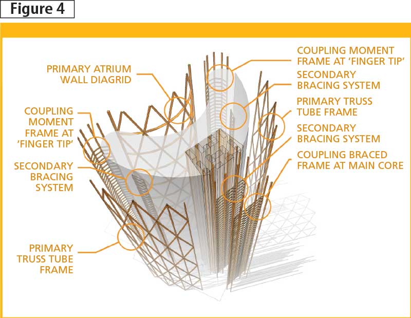
Image courtesy Yolles, A CH2M HILL Company
This hybrid LFRS involved three primary braced frames on the curved south elevation and the two northerly facing ones, ‘coupled’ together with steel moment-resisting and braced frames. To augment the tower’s lateral stiffness between the six-storey-spaced ‘nodal floors,’ a secondary bracing system consisting of conventional steel braced frames at two remote finger-core stairs and around the main central elevator core were also provided.
Consequently, the lateral system comprises the following four principal components:
- six-storey high diagonal grids are facetted along the building perimeter at the northwest and northeast ends;
- diagrid elements are inter-connected through the core with a series of braced frames between elevators and north stair shafts;
- along the south atrium screen wall face, a similar six-storey modular diagrid spans outside, connected to the bulk of the building by horizontal axial-force members—‘drag-struts’—at the ends; and
- the two dominant diagonal grid elements are inter-connected at the ends of the building (‘fingertips’) with a series of rigid frames.


you need to make a section with the list of materials please.