An introduction to gypsum shaftwall systems

By Pamela M. Shinkoda, P.Eng., CSC
Shaftwall systems are a crucial component in the design and construction of commercial buildings, serving a variety of important functions for the structure. They house elevators and stairwells, as well as HVAC, telecom, and electrical equipment. However, their most important function is to provide an extra layer of fire resistance between two adjacent areas of a building—such as an elevator shaft and hallways—to help protect building occupants during a fire scenario.
With these factors taken into consideration, it is important for architects to understand the components of gypsum shaftwall systems and where and how they are typically used. This article reviews some of the basics of shaft design that are independent of materials and illustrates some of the fundamental features of shaftwall design by comparing the traditional masonry shaftwall with its more contemporary gypsum counterpart.
Design essentials
A shaft is any enclosed space that extends vertically through one or more floors of a building, connecting successive floors and/or the roof. A shaft may consist of:
- the opening in which elevator cars travel;
- exit stairways;
- vertical HVAC chases;
- telecom and electrical chases;
- laundry chutes; and
- dumbwaiters.
There are two standard approaches to the design of shaftwall systems that influence the material type used to build the shaft wall—masonry and gypsum.
Masonry
In more traditional shaftwall designs, architects create a structure that encloses the shaft before construction of the building that surrounds it. This approach typically uses concrete masonry units (CMUs) or poured concrete.
Since the basic task of the masonry shaftwall is to support itself and provide fire ratings, it needs to be structurally sound and fire-resistant. Its dense mass provides good sound attenuation, keeping noise from the stairwell or elevator confined to the shaft. However, due to their dense mass, masonry shaftwalls require engineering attention to create the footing needed for support.
Additionally, because these shaftwalls are usually erected before the rest of the building, they need their own slot in the construction schedule. Though they rate high on the performance end, masonry systems are also difficult to co-ordinate and install, making them a more time-consuming, expensive part of the project.
Gypsum
Another option involves creating the shaftwall from floor to floor once the building structure has been constructed, precluding the need for a standalone system. About 40 years ago, gypsum board was engineered as a 25-mm (1-in.) shaftwall material that helped make this design approach more popular. Gypsum systems must be constructed of noncombustible components best-suited for the building type being constructed.
Gypsum shaftwall systems offer a more balanced mix of performance and installation benefits. Their components are lightweight compared to masonry, allowing more design possibilities and simplifying the installation—a two-hour fire-resistance-rated gypsum shaftwall system weighs only 44 kg/m2 (9 lb/sf) and is only 95 mm (3.75 in.) thick. In contrast, masonry walls for two-hour fire-resistance are typically 200 mm (8 in.) and weigh between 146 and 439 kg/m2 (30 to 90 psf). Therefore, gypsum wallboard can be installed more quickly and more economically than masonry. Gypsum is naturally fire-resistant as, chemically speaking, it contains water—the material can be written as CaSO4 2H20. (The water is gradually released as vapour during a fire, providing protection until it is all consumed.) The shaftwall systems include acoustic insulation and sealants
to minimize sound transmission from the shaft.
Basic anatomy of a gypsum shaftwall
A gypsum shaftwall system consists of:
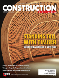
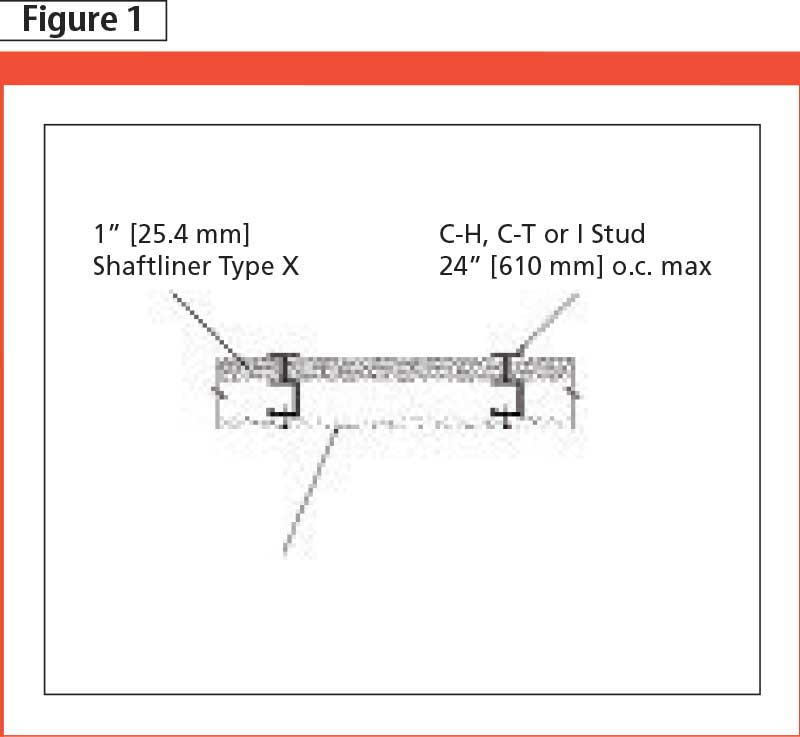
- 25-mm (1-in.) gypsum shaftliner panels;
- Types X or C gypsum board;
- studs; and
- J-tracks.
Gypsum shaftliner panels are 25 mm thick, 609 mm (24 in.) wide, and come in lengths of 2.4 to 3.7 m (8 to 12 ft). They are available in three facing options:
- moisture-resistant paper-faced;
- treated mould/moisture-resistant paper-faced; and
- glass mat-faced.
Paper-faced gypsum shaftliners meet ASTM C1396, Standard Specification for Gypsum Board, while glass-mat gypsum shaftliners meet ASTM C1658, Standard Specification for Glass Mat Gypsum Panels. The latter are moisture/mould-resistant and can be exposed to normal weather during construction.
Types X (fire-resistant) and C (improved Type X) gypsum board are installed in one or more layers on the corridor side of the shaftwall system. The number of layers typically equals the hourly fire resistance rating of the shaftwall system. Each board meets requirements for ASTM C1396. In addition to fire resistance, abuse-resistant Type X gypsum boards provide resistance to impact and surface abrasions.
Manufacturers of steel framing produce three different profiles of shaftwall studs:
- C-H;
- C-T; and
- I.
The studs are installed 609 mm (24 in.) on centre (oc) to match the width of the shaftliner panels. Common gauges for metal studs are 0.454 and 0.835 mm (i.e. 25 and 20 gauge), and common depths are 64, 102, and 152 mm (2.5, 4, and 6 in.).
J-tracks provide a way of anchoring the shaftwall to the existing structure. A J-track is used at the terminal ends, top, and bottom of shaftwall assemblies and is anchored to the concrete slab, existing walls, or structural steel framing. J-tracks have three depths—64, 102, or 152 mm—as chosen to match the depth of the stud. The thickness of the J-track is also chosen to match the gauge of the stud.
Sign up for our weekly newsletter
Construction Canada weekly newsletters give the latest AEC industry news for those who build, design, engineer, specify, renovate or operate in the built environment.
Products & Services


Read the Latest Issue