The three Ps of prefabricated EIFS: Preparation, production, placement
By Alex Ardelean, Elizabeth V. Rodenkirch, and Peter M. Babaian
In its most general form, exterior insulation and finish systems (EIFS) consist of expanded polystyrene (EPS) insulation board coated with a reinforced polymer-modified cementitious base coat and a polymer-based finish coat. Other less commonly used types of rigid insulation boards in EIFS include extruded polystyrene (XPS), polyisocyanurate (polyiso), and mineral wool. Drainage EIFS, unlike barrier EIFS, includes a dedicated water-resistive air barrier (WRAB) and drainage plane.
EIFS is lightweight and uses relatively few materials. It is typically adhered in place, eliminating cladding anchorage penetrations through the WRAB. EIFS-clad wall panels can be fully prefabricated, from the structural backup to the finish coat. EIFS adhesives, typically polymer-modified cementitious materials, are compatible with many WRAB chemistries. EIFS provides continuous insulation (c.i.) on the exterior of the building, which increases the effective thermal resistance of the assembly. EIFS can be readily sourced from several manufacturers, many of which have already performed numerous assembly tests, including fire performance, bond strength, impact resistance, and drainage efficiency, among others, and obtained assembly approvals in major jurisdictions. EIFS is also a cost-competitive cladding in many markets. As a result, EIFS has become an attractive cladding option for use in prefabricated wall panels, in which EIFS materials are shop-applied to sheathing and metal stud backup wall construction under controlled conditions. Prefabricated panels may also include fenestration and other elements of the exterior wall.
Despite its potential benefits, EIFS has limitations that must be considered when used as a prefabricated wall panel cladding. By having continuous and often flammable insulation on the exterior side of the wall, EIFS is susceptible to melting, ignition, and fire propagation. It is prone to impact damage during transportation, installation, and service, particularly at panel edges. Where field repairs or modifications are necessary, it can be challenging to repair the prefabricated panel in the field in a way that restores WRAB continuity and provides a matching finish texture. While fully adhered systems offer certain advantages, their water management performance depends entirely on the quality of the installation, specifically, the quality of the drainage plane, which is rarely verified. As with any prefabricated panel cladding, joints and transitions to adjacent enclosure systems require significant forethought and planning while considering constructability in the shop and the field.
One can realize the schedule and quality benefits of prefabricated EIFS-clad wall panel construction by following the three “Ps”: ensuring appropriate scope and detailed design during “Preparation,” implementing robust quality assurance and control processes during “Production,” and executing effectively during “Placement.”
Preparation
Scope
A portion of most prefabricated cladding construction projects will inevitably require field installation. Successful prefabricated cladding projects delineate the prefabricated and field-installed portions of the work. Prefabricated construction is usually conducted through delegated design and affects many project stakeholders, so it is important to have all parties aligned as early as possible during design. Engaging a contractor, a delegated designer, and a fabricator early in design to provide insights on scope, construction sequencing, and cost can help streamline the design and construction process.
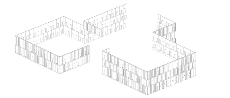
Establishing the prefabricated construction scope depends on the project’s type, location, and frequency of unique details. Ideally, prefabricated cladding is installed continuously and uninterruptedly by a single subcontractor with minimal mobilizations. Unique details require coordination and sequencing with other trades, interrupting the prefabricated cladding installation and increasing the risk of mistakes and re-work. These details can negate the schedule and/or cost savings that prefabrication can offer. The contractor should create a register of all unique details associated with the prefabricated construction scope. The register can be used to identify the trades and sequencing required with each detail and to keep track of changes in detail over time due to changes in design. Three-dimensional models help identify unique prefabricated construction details to populate the detail register (Figure 1). Models need not be extensively developed for this purpose; this work can be done early in the prefabrication subcontractor’s design and shop drawing process.
In tandem with determining the prefabricated scope of work, the project team, in consultation with the delegated designer, fabricator, and manufacturer, must determine which parts of the wall panels are prefabricated and installed in the field. Wall panels may be fabricated as full assemblies (from the structural backup out to and including the EIFS cladding and fenestrations), bare assemblies (only the structural backup and sheathing), and other partial assembly configurations in between. Generally, full assemblies yield the most schedule savings and take advantage of prefabrication’s enhanced quality assurance and control. Cost, sequencing, and transportation logistics are reasons a project team may elect to fabricate a partial assembly.
Joint type
One of the most critical and challenging aspects of designing prefabricated wall panels, EIFS-clad or otherwise, is providing continuity of the four barriers, thermal, water, air, and vapour, across joints between prefabricated panels and transitions to adjacent enclosure systems.
Joints between prefabricated panels and adjacent enclosure systems that must be given special consideration include:
- Panels to below-grade waterproofing.
- Panels to grade (landscaping and hardscaping).
- Panels to exterior doors.
- Panels to field-installed exterior wall systems.
- Panels to through-wall movement joints
(e.g. expansion joints). - Panels to roofing systems:
- Where the roofing transition is at the base of the panel in a rising wall condition.
- Where the roofing transition is at the top of the panel in a parapet condition.
There are two common joint types in prefabricated construction: butt joints and shiplap joints. Butt joints provide a basic level of weather protection and require less work than shiplap joints during prefabrication and installation but rely heavily on the proper application of joint sealants.
Shiplap joints offer redundancy in weather protection due to their inherent layering that sheds water, but they require additional work in fabrication and field installation. During fabrication, panels are fitted with one-half of the shiplap joint, and in the field, adjoining construction, such as concrete curbs at grade, is prepared with the receiving end of the shiplap joint (Figure 2). Preparing the receiving end of the shiplap joint in the field generally involves one subcontractor installing the joint framing and another flashing the framing to integrate it with the adjacent enclosure. This additional work may require multiple subcontractors to make several passes at a detail during construction, depending on how it is bought out and coordinated by the contractor.
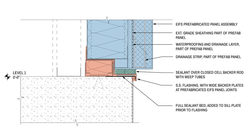
The receiving end of the shiplap joint (the red area in Figure 2) is usually constructed by multiple subcontractors, as described here. The blue and green areas in Figure 2 may be in the scope of two other separate contractors. If that is the case, there is relatively more coordination and sequencing required by the contractor of the four various subcontractors that could be engaged to construct this detail (cold-formed framing and insulation, metal flashing and sealant bed, prefabricated panel, and joint sealant).
To reduce the coordination required, the contractor may “buy out” or group some of the scope under fewer separate subcontractors, e.g. one subcontractor does all the cold-formed framing, insulation, sealant bed, and metal flashing instead of two separate subcontractors. This requires forethought by the contractor and project team in the bidding process.
Wall panels with shiplap joints may also require installation in a particular order on the building. The prefabricated wall panel shiplap joint installation sequence should be established early and fully coordinated to schedule other subcontractors’ work accordingly.
Joints can occur more frequently in prefabricated EIFS-clad wall panel construction than in traditional field-installed EIFS construction. Trucking limitations and crane capacities often limit prefabricated panel joint frequency/spacing. Panels must fit on the trucks transporting them to the site and in the trucks’ lanes. They must also be safely handled during installation and hoisted onto the building.
Joint width
The type and magnitude of the anticipated wall panel movement and joint sealant limitations govern wall panel joint widths. Code-based structural requirements determine the minimum joint width; simply put, panels must not collide during service-level movement. Service-level movement includes building movements (inter-story drift, floor deflections, and thermal stresses) and panel movements (thermal stresses). Owners can further enhance the structural performance of the wall panels beyond the code-based requirements by using prescriptive criteria based on the owner’s tolerance to risk.
Seismic areas, high-importance structures, and especially the combination thereof generally have the most demanding structural requirements. These requirements are typically met by designing larger joints between wall panels, specifying joint sealants with high movement capabilities, locating panel collision points away from higher-risk areas of the building (i.e. emergency egress and assembly areas), or providing crumple zones in the cladding (areas where it is deemed acceptable for the cladding to crush during movement that exceeds service levels).
On the other end of the spectrum, the maximum joint width is determined by the movement capacity of the sealant material. Gun-grade silicone sealant can be installed into a maximum joint width of 102 mm (4 in.).1 Some manufacturers suggest even stricter joint width limits when using silicone sealants and even stricter still with other sealant chemistries. As the sealant joint width increases, the sealant’s movement capability suffers, and it becomes increasingly difficult to install the sealant reliably, especially on vertical surfaces.
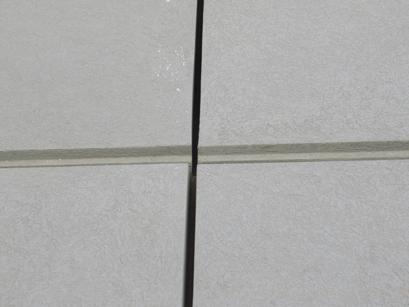
Designers and specifiers must also carefully consider panel fabrication and installation tolerances because they directly affect panel joint widths. Irregular joint widths can occur due to various fabrication-related issues, including a buildup of material at panel edges and imprecise panel size and squareness (Figure 3). Installation issues generally include wall panels not being installed plumb; sometimes, this can be caused by superstructure installation tolerances that cannot be accounted for by the panel anchorage.
Designers should consider the appropriate combination of tolerances and anticipated movements when determining panel joint widths. As a result, typical joint widths between prefabricated wall panels and adjacent wall systems can differ from those between prefabricated wall panels.
Repairs
Often overlooked, planning for wall panel repairs early in the design process is critical. In the authors’ experience with prefabricated EIFS-clad wall panel construction, some panels will likely require field repairs or replacement after installation due to construction damage, field modifications, or other unforeseen conditions. Mockups of field repairs should occur before the construction phase to establish standards of what constitutes repairable damage or modification (versus damage or modification that requires full panel replacement) and specify field repair and finish requirements that result in a product acceptable to the owner. It is helpful to include these requirements and procedures in an operation and maintenance manual for the owner/operator at project turnover to address in-service damage.
Due to wear and age, panel components will require repair or replacement. Joint sealants and fenestrations, among other components, are expected to deteriorate and should have an associated inspection, maintenance, and replacement schedule. Give special consideration to means of access for inspection and maintenance activities. It is also important to consider how noise, vibration, and particulate emissions will be controlled during field repairs and replacement work.
Production
Quality assurance/quality control (QA/QC)
Prefabricated construction lends itself well to robust QA/QC programs. The project team should establish and vet QA/QC processes well before fabrication and ensure they align with the owner’s project requirements and contract documents.
QA documentation should include information regarding product batch numbers, material manufacture and expiration dates, material installation dates, environmental conditions at installation, as well as installation procedures.
QC documentation should include testing procedures, environmental conditions during testing, testing apparatus information and calibration dates, testing results, and a description of where the testing occurred on the panels and panels tested. It should also include the sizes of the panels, including squareness at corners and flatness along edges, as well as cladding thickness measurements.
Prefabrication allows the panels to be staged so all panel components and surfaces are easily accessible for inspection and testing. Prefabricated panels are typically constructed on horizontal surfaces, eliminating the need to work at heights and preventing hazards such as falls.
Prefabricated EIFS panel testing should include wet and dry film thickness testing for fluid-applied WRAB, adhesion testing for fluid-applied and self-adhered WRAB, transition materials, and flashings to the panel sheathing, adhesion testing for the EIFS insulation to membranes and flashings, and adhesion testing for joint sealants at all sealant-substrate combinations planned for use in the field; this includes sealant-substrate combinations to adjacent construction by others. Special inspections of the WRAB must be performed where required by the applicable building code. Metal flashings and diverter tracks can be examined to ensure a positive and outward slope. Under controlled conditions in a factory setting, metal flashings and diverter tracks should be continuous and installed without joints; however, if they occur, they should be examined to ensure they are watertight.
Logistics
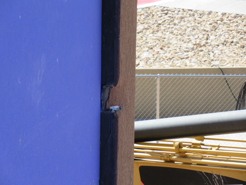
The fabricator must consider logistics, including transportation and packaging when determining which panel components are installed at the shop. Some panel components are at higher risk of damage during handling and transportation. EIFS is especially sensitive to transportation-related damage from lifting and strapping, particularly at panel edges (Figure 4).
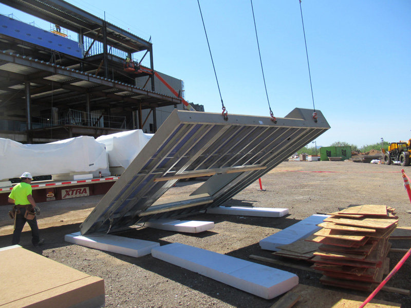
Designated lifting locations (Figure 5) and touch points for strapping panels to the trucks should be marked on each panel and reinforced in the panel packaging, on the panels themselves, or both. Panels with protruding elements, such as EIFS features, penetration sleeves, or other appurtenances, should also be packaged and oriented thoughtfully during transport to avoid damage.

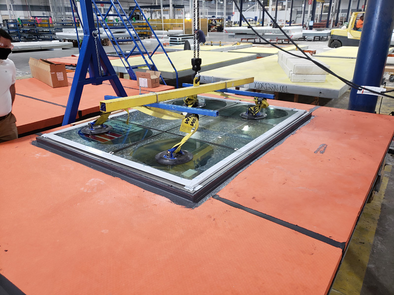
Modern glazing systems offer solutions that can be fully shop-installed (Figure 6), fully field-installed, or partially installed in both. An example of a partially pre-installed window is a flanged, receiver-set system. The flanged receiver framing is fully set in the rough opening, treated at joints and corners, and integrated with the panel WRAB in the shop. The glazing and glazing seals are packaged separately and set into the pre-installed receivers in the field. This is an effective way to provide a robust window installation that takes advantage of the enhanced QC in the shop when integrating the window flanges and minimizes risk during transportation by leaving the glazing out of the prefabrication portion of the work. As part of selecting the panel scope during “Preparation,” the project team should consider the logistics to handle transport panels with pre-installed windows safely.
When incorporating air-sealed systems like insulated glass units (IGUs) into prefabricated wall panels, consider whether pressure equalizing is necessary. Over a sustained period, a large change in elevation between where the IGUs are sealed and the project site causes stresses in the IGU seals due to the difference in air pressure inside and outside of the IGU. This can lead to early deterioration of the IGU. The pressure difference can also lead to the bowing of the glass panes and visual distortions.
Mockups
Construct mockups that maximize the project-specific prefabricated wall panel conditions. Mockups are beneficial for the design team to evaluate the esthetics of the construction and for the fabricator to train installers in specific installation roles and techniques, especially for unique details. Approved mockups should be protected and used to establish the technical and esthetic requirements of the completed work. Consider assigning shop staff exclusively to install shop-fabricated components of the mockups and, conversely, field staff exclusively to install field-installed components of the mockups as a training and teaching exercise; this applies to visual and performance mockups if there are multiple.
Mockups should contain all typical conditions, including the field of wall finishes and textures, fenestrations, appurtenances, typical penetrations, and panel joints, including back-wrapped and edge-wrapped panel edges (Figure 7). The authors also recommend including field repairs in the mockup.
It can be advantageous to construct and display mockups off-site, but consider that the esthetic evaluation of some components is better suited for the project site, with site-specific exposures, adjacent cladding systems, nearby buildings, landscaping, and hardscaping, among other conditions.
Performance mockup testing can be very valuable when specified appropriately. Certain tests can occur on individual panels at the shop, and others must occur on the building as part of the permanent construction. Testing that can be performed at the shop is generally more cost-effective for the testing itself and subsequent diagnostic and repair efforts. Testing should be performed as early as possible to identify and repair systemic issues before the issues are replicated.
Placement
Joints
Joint sealant performance depends on the quality of the sealant installation. To ensure consistent results, limit joint sealant installers where possible. Consider employing a project-specific certification system for the installers using the visual and performance mockups (i.e. installers that produce joints acceptable to the design team on the mockups are approved to install joint sealants on site for the project).
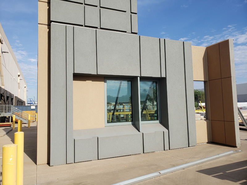
Designers can also significantly impact joint sealant installation success in providing clearance for joint sealant installation. Consider the space provided between prefabricated panels that include the cladding and finishes; the thicker the cladding, the less access installers have to the joint where they need to install sealant, and the more unreliable the joint sealant installation is. Inspection and maintenance of the joint sealants would be equally as unreliable. Since prefabricated panels are generally installed 12.7 to 25 mm (0.5 to 1 in.) apart, the authors suggest the cladding thickness is limited to 76 mm (3 in.) immediately adjacent to panel joints. Stepping the cladding thickness down at panel joints using reveals or chamfered edges can provide reasonable clearance to panel joints while maintaining thicker cladding in the field of the panel (Figure 8).
Field penetrations
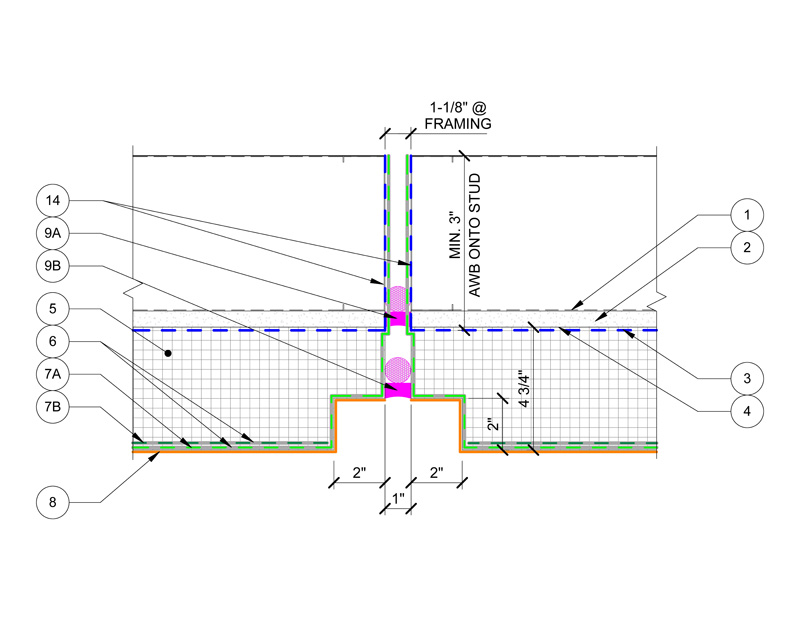
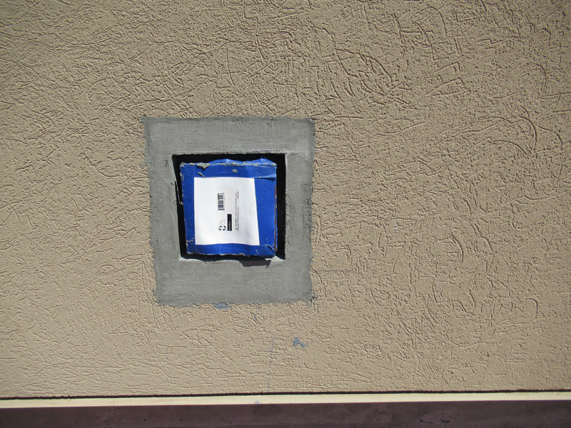
Penetration locations should be coordinated so that flashed openings can be prefabricated; however, some field penetrations during construction are inevitable. The repair area for field penetrations is always larger than the penetration area itself. It includes the penetration, the gap between the penetration and the panel, and the space required to adequately integrate the penetration flashing to the panel WRAB (Figure 9). Subcontractors can perform field repairs without delay for design approval using the pre-approved repair criteria and procedures established during “Preparation.”
The contractor should engage subcontractors that require exterior wall penetrations, such as mechanical, electrical, plumbing, security, and signage, as early as possible during subcontractor procurement to finalize penetration requirements and locations. These requirements should be monitored as part of the detail register and closely coordinated between the contractor, relevant subcontractors, the delegated panel designer, and the panel fabricator.
Conclusion
With appropriate coordination during “preparation,” “production,” and “placement,” one can successfully use EIFS in their next prefabricated wall panel project:
- Preparation: Determine an appropriate prefabrication scope of work; be proactive in design detailing by considering construction and maintenance constraints.
- Production: Make the most of shop fabrication by implementing the right quality assurance and control processes; full advantage of mockups; package wall panels thoughtfully and strategically, not only for installation but for all steps in between, including careful handling and transportation.
- Placement: Execute within the project tolerances; manage field issues using established project procedures.
The items presented here are based on the authors’ experience, are focused on prefabricated EIFS-clad wall panels, and are by no means an exhaustive study of the benefits and challenges of prefabricated construction. They convey the importance of appropriately planning for prefabricated EIFS-clad wall panel use on buildings and provide a road map to identify potential issues affecting the project.
Notes
1 Refer to Dow Building Science’s Dow Construction Sealants Technical Manual (Americas); The Dow Chemical Company, Midland, MI, 2024.
Authors

Alex Ardelean, P.E., P.Eng., is a consulting engineer with Simpson Gumpertz & Heger (SGH) in Chicago, Ill. His experience includes investigation, design, rehabilitation, building enclosure commissioning, and field testing for new and historic building enclosures. He can be reached at aardelean@sgh.com.

Elizabeth Rodenkirch, AIA, LEED AP BD+C, is a senior consulting architect with SGH’s building technology group in Chicago, Ill. Her expertise focuses on building enclosure and sustainability, failure investigation, materials testing, and evaluation of resilient flooring systems. She can be reached at evrodenkirch@sgh.com.

Peter Babaian, P.E., S.E., P.Eng., is a principal in SGH’s Chicago, Ill., office and serves as the building technology division head. His projects involve exterior enclosure consulting for new construction, rehabilitating existing structures and enclosures, historic preservation, building enclosure commissioning, investigating non-performing building enclosures, and providing expert services related to construction litigation. Babaian can be reached at pmbabaian@sgh.com.
Sign up for our weekly newsletter
Construction Canada weekly newsletters give the latest AEC industry news for those who build, design, engineer, specify, renovate or operate in the built environment.
Related Products & Services

Read the Latest Issue