Freestanding roof guard woes
Understanding staged structural failure analyses
By Bill Yao, P.Eng.
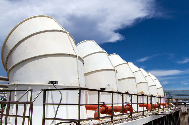
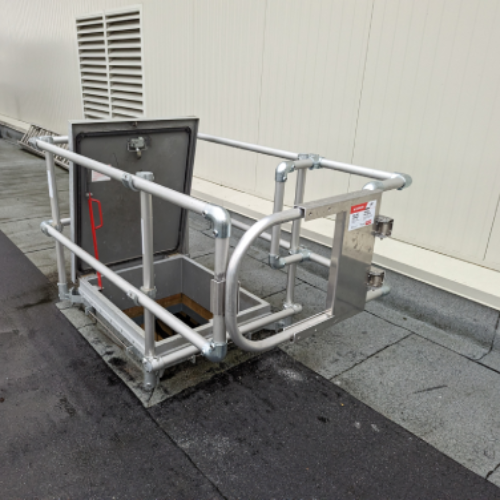
HVAC equipment is generally installed on top of the flat roofs of industrial, commercial, and institutional buildings. The maintenance personnel sometimes are exposed to danger of falling if the units are close to the roof’s edges. In this case, a guardrail system is required by Ontario Ministry of Labour Regulation 851, the Occupational Health and Safety Act. The regulation also specifies a guardrail shall be constructed to meet the structural requirements for guards as set out in Ontario Building Code (OBC), which has been adopted from the National Building Code of Canada (NBC) 4.1.5.15.
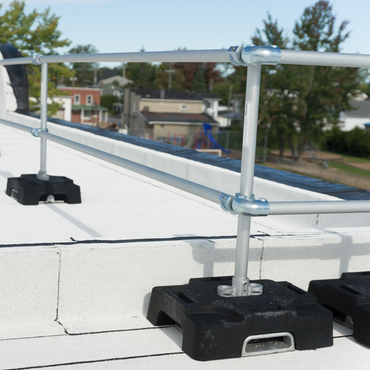
Set up at the edge of the roof, these guardrail systems are laid directly on a flat roof without any anchors penetrating through. This means the stability to resist a concentrated load specified in the province’s code fully depends on its integrity and the balance weight of the base plates.
A guardrail system generally consists of three components:
- 610 x 610 x 25-mm (24 x 24 x 1-in.) steel base plates;
- 32-mm (1 ¼-in.) Schedule 40 steel pipes; and
- special pipe fittings that connect the posts and horizontal rails together by a sleeve and set-screw mechanism. (The vertical posts are also installed to the 25-mm [1-in.] thick base plates through sleeves and set screws.)
Design standards for a guardrail system are specified in the 2012 OBC under 4.1.5.14. (“Loads on Guards”):
1. The minimum specified horizontal load applied inward or outward at the top of every required guard shall be,
B. A concentrated load of 1.0 KN applied at point for access ways to equipment platforms, contiguous stairs, and similar areas where the gathering of many people is improbable.
The question is, how can one be certain a guardrail system will protect those on a roof? This article suggests an analysis option to determine structural success.
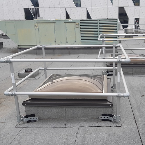
The setup
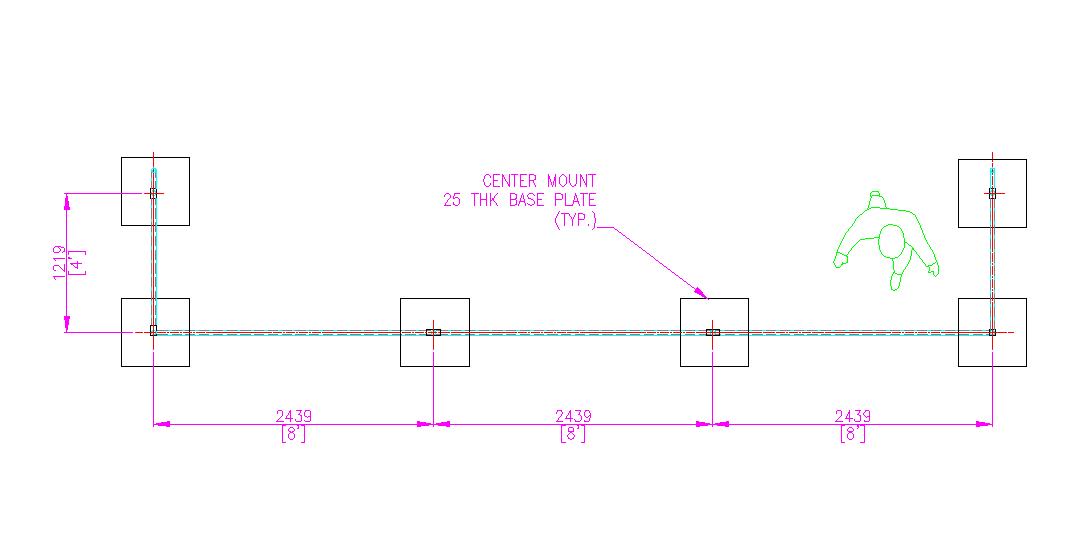
A typical three-bay guardrail system is set up on a gravel protected roof. The vertical posts of the system are spaced at 2.4 mm (8 ft). The vertical posts are installed to the base plates, and a 1219-mm (48-in.) long outrigger is attached at each end to increase the system’s stability. The plan view of the guardrail system is shown below.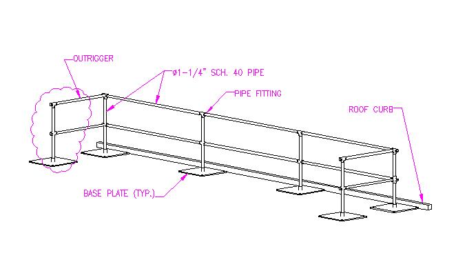
In this scenario, there are the following assumptions:
- all rails and posts are rigidly connected;
- friction co-efficient of steel plate to roof’s white gravel is 0.3;
- self-weight of the rails and posts is ignored (to be conservative);
- slip of front base plates is also ignored due to the assumption they are against the roof curbs; and
- bending moments/shear forces of every base plate are checked to determine whether the base plate fails or not.
For the analysis, the initial calculations were as follows:
- self-weight of a steel base plate= 0.609 × 0.609 × 0.025 × 7.85= 72.8 kg (0.728 KN);
- resisting moment per a base plate= 0.728 × 0.305= 0.222 KN-m;
- friction force per a base plate= 0.728 × 0.3= 0.218 KN;
- over-turning moment= 1.06 KN-m; and
- a concentrated load of 1.0 KN (unfactored) applied outward at the top rail of the system.
At the beginning, the guardrail system stands there with all posts fixed. When a point load is applied and slowly increased, the first post would reach its breaking point in which the bending moment is 0.222 KN-m, or lateral shear force is 0.22 KN, then the base plate will rotate or slide. If the load increases, it will be transferred through the rails to the other base plates, which will rotate or slide—either the whole system stably stands or completely collapses.
The guardrail system will change its stability mode during the loading process. Or, in other words, the analysis model will change. Therefore, the general structural analysis is unsuitable for this situation.
Sign up for our weekly newsletter
Construction Canada weekly newsletters give the latest AEC industry news for those who build, design, engineer, specify, renovate or operate in the built environment.
Related Products & Services

Read the Latest Issue