Blindside waterproofing: Strategies to mitigate installation surprises
By Julia H. Schofield, PE, Sam S. Zalok, PE, and John N. Karras, PE
The practice of blindside waterproofing, where the membrane is pre-applied to an excavation support system outboard of the concrete foundation wall, has a decades-long history of use on commercial building projects, and yet it is not uncommon for contemporary projects to face unwelcomed surprises at the time of the waterproofing installation.
These scenarios can force the team to scramble and either reluctantly accept installation details that may compromise the intended performance or consider time-consuming or costly changes to the waterproofing or building design.
In this article, the authors highlight their experience with certain design decisions, site conditions, construction methodologies/materials, and service penetration configurations that are often disjointed variables that continue to be common sources of blindside waterproofing surprises. The authors provide recommendations for anticipating and integrating these variables into a co-ordinated blindside waterproofing design.
Support of excavation and foundation structural design
Support of excavation (SOE) is a common approach to enable the construction of below-grade building space. In addition to providing earth retention, the SOE serves as the substrate for the blindside waterproofing membrane, and the SOE structural features (e.g. tiebacks, bracing) that penetrate the waterproofing must be addressed with flashing details. Consequently, the SOE system and its features are integral to the blindside waterproofing system.
The final SOE design is typically delegated to the SOE trade contractor and their specialty engineer. The SOE delegated designers and the designer of the below-grade waterproofing system (e.g. the architect or their waterproofing consultant) seldom share an integrated design process; therefore, the SOE design may inadvertently incorporate features that create waterproofing performance vulnerabilities. Some of these features are summarized below:
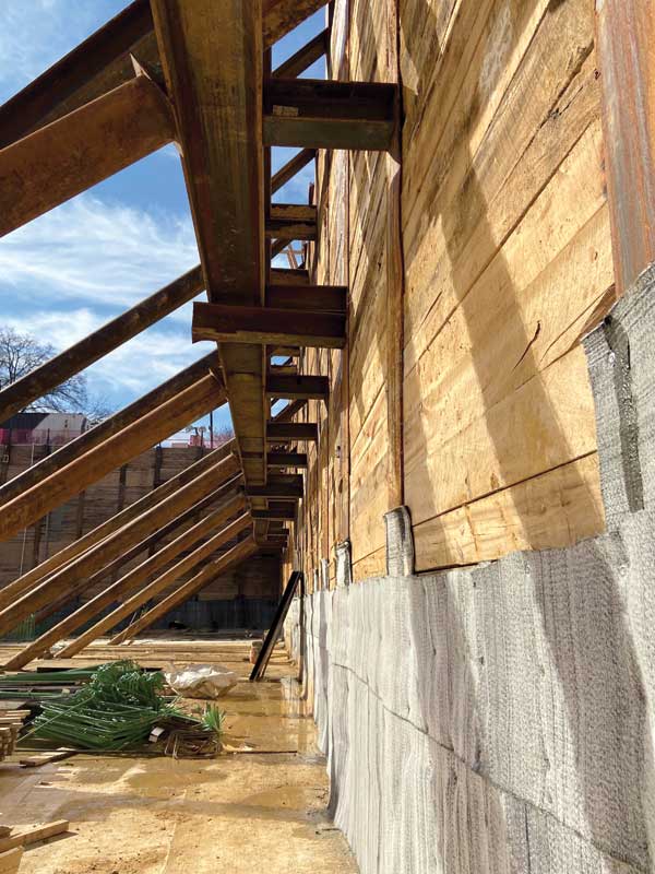
Adding shear studs between soldier piles and the building foundation
Some structural foundation designs incorporate hundreds or thousands1 of shear studs welded to the SOE (Figure 1). The penetrations can be treated with the waterproofing manufacturer’s standard details, but they are costly and inherently increase performance vulnerability for the waterproofing by (a) creating permanent penetrations that rely on sealants/mastics to resist water leakage rather than a continuous membrane, and (b) reducing the margin-for-error by increasing the waterproofing system’s dependency on workmanship sensitive details.
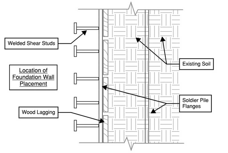
Double waler seats or double knee-braces
Some SOE designs incorporate doubled-up waler seats or braces (Figure 2) in such close proximity to each other (e.g. 25 mm [1 in.] or less) that flashing sheets or sealants cannot be properly constructed in the space between the two. Sometimes project teams consider injectable waterstops, which in general can be helpful supplemental accessories for challenging below-grade waterproofing details, for these conditions. However, reliance on chemical grout injection from the waterstop inherently leaves the detail more vulnerable to water leakage than if the structural members are spaced (approximately 200 mm [8 in.] minimum apart) to allow the application of sheet flashing membranes that turn onto the structural member. Better yet, sometimes the doubled-up members (or SOE braces in general) can be, with permission from the SOE designer and structural engineer, removed before the waterproofing installation. This practice eliminates the penetration altogether, which benefits the waterproofing performance.
Back-lagged soldier piles
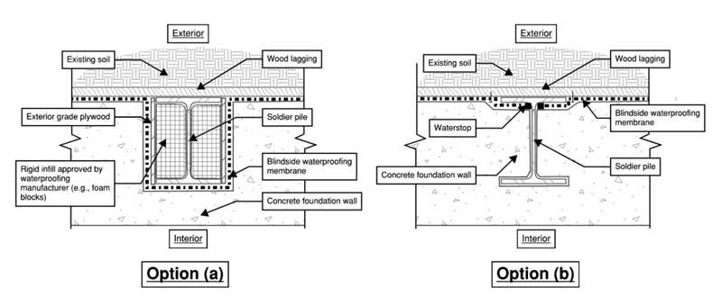
While most soldier-pile-and-lagging SOE systems (which are prevalent in the mid-Atlantic where the authors are based) incorporate wood lagging at the building-side flange of the soldier pile (favourably creating a relatively planar substrate for the blindside waterproofing membrane), SOE designers sometimes elect to position the lagging outboard of the outer flange of the soldier pile (i.e. soil-side flange) in what is referred to as a “back-lagged” configuration. Other times, back-lagged piles may be the consequence of misdriven or field-relocated piles to avoid a buried obstruction.
If back-lagging is necessary, the blindside waterproofing membrane must either: (a) contour around each soldier pile with additional details, such as infilling of the web space with rigid materials authorized by the waterproofing manufacturer, or (b) the waterproofing membrane must be interrupted at the web of each soldier pile. Both options (Figure 3, page 28) typically trigger complications requiring the structural engineer’s evaluation and may result in reinforcing bars needing to pass through each pile (possibly penetrating the waterproofing membrane) or the need to introduce structural pilasters to accommodate interruptions of foundation reinforcing. Option (a), especially if not captured by a co-ordinated design in the base bid, can be prone to change order requests to somewhat of a greater degree than option (b). Option (a), however, is significantly more reliable than option (b), which does not result in waterproofing membrane continuity and relies on sealants/mastics to terminate the waterproofing membrane at every pile flange, creating a waterproofing performance vulnerability at each back-lagged pile.
Geotechnical/environmental considerations
The project site’s subgrade and environmental characteristics, which are reported in a geotechnical report (and/or an accompanying environmental report), have fundamental relevance to blindside waterproofing design.
The geotechnical report typically incorporates a subsurface site investigation with soil borings and describes a recommended subgrade drainage strategy (if applicable). It suggests the design groundwater table elevation and describes the potential for fluctuating or perched groundwater.2 If the lowest floor level is near or below the groundwater table, the waterproofing and foundation must withstand hydrostatic conditions unless the site is permanently de-watered. Permanent subgrade dewatering systems may be feasible for certain circumstances,3 but they add perpetual operational costs and maintenance demands to the building. Such maintenance costs/demands can be significant and associated with the clearing of the under-slab drainage piping, construction and maintenance of emergency power generating systems, maintenance of sump pumps, and treatment of contaminated groundwater, if applicable. Many below-grade waterproofing manufacturers have enhanced details for waterproofing membranes when used in a hydrostatic versus non-hydrostatic condition.
The geotechnical report also typically indicates the existence of soil or groundwater mineralogical attributes such as iron ochre (also called iron bacteria), or hazardous contaminants, which may classify the area as a “brownfield site.”4 Many contaminants found at brownfield sites, such as laundromat chemicals, or oils from a former gas station (or associated hydrocarbons), can degrade an improperly selected waterproofing membrane or accessory materials, such as tapes and sealants, and the contaminants (subject to local regulations) may require the use of specialized membranes which function as a gas barrier for the below-grade enclosure. If iron ochre is found at the site (a scenario the authors have seen occur in the Washington, D.C. area for example), its presence can clog or diminish the water flow of subgrade drainage piping over time, necessitating frequent cleaning of the drainage lines in service. Further, if the geotechnical site investigation identifies other geotechnical conditions (e.g. expansive soils), additional considerations may affect or preclude the viability of an under-slab drainage system.
Concrete placement method and formwork/reinforcement materials
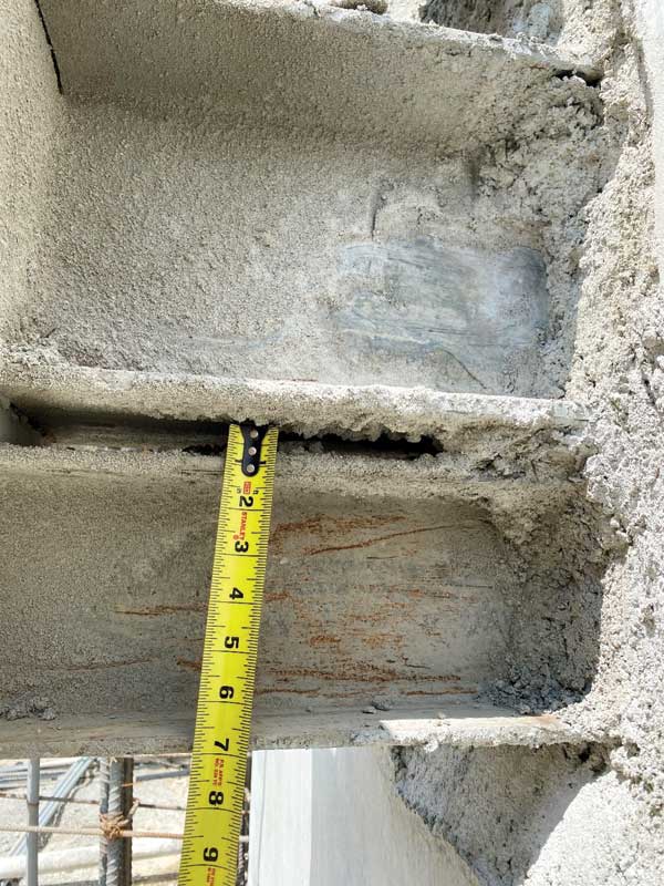
Shotcrete
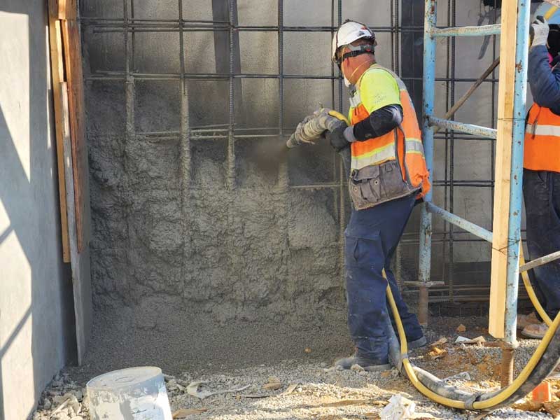
Project teams often elect to use the cast-in-place concrete placement method for below-grade foundation structures, but in some U.S. regions, they either favour or increasingly consider the shotcrete method (Figure 4, page 30). Shotcrete is a pneumatically applied concrete mix fired against the blindside waterproofing membrane at a high speed of approximately 19 to 30 m/s (65 to 100 ft/s),5 and the use of shotcrete demands co-ordination with the blindside waterproofing design. Some shotcrete/blindside waterproofing considerations include the following:
- The shotcrete application can cause waterproofing membrane seam blowout failure or puncture the blindside membrane due to the velocity of the aggregate projection.
- The rebar cage requires stabilization to the SOE, and in some cases, stabilization anchors remain as permanent penetrations in the blindside waterproofing, requiring treatment with appropriate flashing details. For similar reasons as the shear studs between soldier piles and the building foundation discussion, these penetrations tend to increase performance vulnerability for the waterproofing system.
- Concrete overspray (i.e. when concrete splatter from the shotcrete application lands on an adjacent piece of membrane and cures before that portion of the wall is placed) can detrimentally affect the bond of the shotcrete to the waterproofing; this bond is necessary for most blindside waterproofing membranes to resist the lateral migration of water as intended.
- “Shadowing” (i.e. thin areas and voids) around dense areas of rebar, can affect the structural quality of the wall placement and can be detrimental to concrete-to-membrane bond (refer to the lateral migration resistance discussion).
- Many blindside waterproofing membranes require the sustained confining pressure to perform as intended,6 and improper shotcrete execution can result in inadequate or non-uniform confining pressure.
Based on these potential pitfalls, waterproofing manufacturers may not authorize the use of shotcrete with some of their blindside waterproofing products, or they may only authorize their use at limited instances (e.g. non-hydrostatic applications). Waterproofing manufacturers also typically have enhanced detailing requirements, such as more robust seam reinforcement than standard details, when shotcrete is utilized. Some waterproofing manufacturer’s market specific systems are tailored for the shotcrete application.
Formwork/reinforcement materials
With any concrete placement method, the selected concrete formwork materials and reinforcing steel supports must be compatible with the waterproofing system. For example, stay-in-place forms, which are composed of a wire-mesh material, can limit the potential for the waterproofing membrane to establish intimate contact with the concrete, creating unbonded sections which may allow lateral water migration at any membrane breach. For this reason, many waterproofing manufacturers explicitly prohibit the use of stay-in-place forms where blindside waterproofing is present.
Another example of a concrete-related construction material having potential incompatibility with blindside waterproofing is the rebar chair. Rebar chairs elevate the reinforcing steel cage from the face of the waterproofing to allow for adequate concrete cover. However, some chair products have sharp edges at their feet, which can damage the waterproofing membrane. It is therefore common for blindside waterproofing manufacturers to prohibit the use of rebar chairs that lack plastic caps on their feet, and to recommend concrete blocks, pavers, or dobies as less risk-prone methods to elevate the rebar cage. Similarly, for mat slabs that include MEP services which will be routed through the slab, the MEP trade contractor may elect to elevate/brace the piping using stands with sharp feet that bear on and risk damaging the membrane. In this instance, concrete blocks or pavers are appropriate, as are base plate details that some waterproofing manufacturers have developed for this purpose.
Duct banks
In general, the most reliably watertight below-grade service penetrations through blindside waterproofing are those in which each penetration has enough clear space around it, such that it can be individually flashed. Duct banks, however, which are composed of a cluster of closely spaced electrical conduits, are influenced by utility providers and electrical contractors not ordinarily integrated with the waterproofing design process. Often sequenced for installation after the placement of the foundation wall, duct banks commonly bring a layer of complexity and unpredictability to the below-grade waterproofing process. Consequently, surprise outcomes in the field where the duct bank configuration bears no resemblance to the waterproofing design or shop drawing details can leave construction teams scrambling for guidance at time-sensitive portions of the project.
With foresight and design co-ordination, below-grade waterproofing designs can achieve sound waterproofing principles and compatibility with project-specific duct bank configurations. Some example approaches include the following:
- If the duct bank is encased in concrete (i.e. the space between the individual conduits is filled with concrete), treat the duct bank encasement as one large penetration, and apply flashing (extending away from the foundation wall for a few metres or so) onto the concrete. Since this work would take place from outside of the foundation wall after it has been placed, the design can incorporate a positive-side-applied flashing detail (using a self-adhered membrane) on the top and sides of the duct bank concrete encasement, and a blindside flashing detail (using an under-slab waterproofing membrane) on the bottom. Also consider installing the top of the concrete encasement with a slight slope to drain off the sides for a performance benefit.
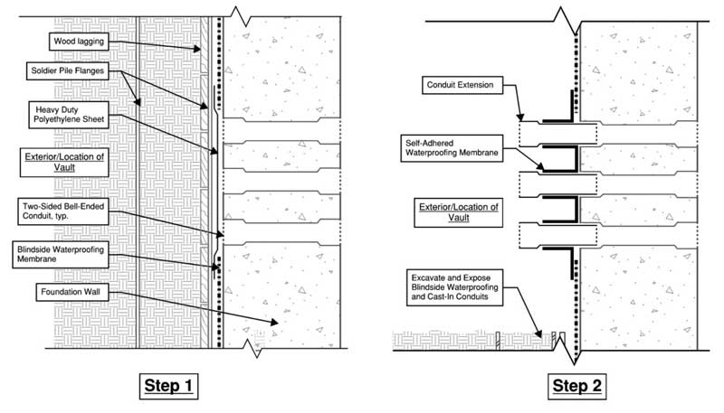
- If the utility provider agrees to allow approximately 100 mm (4 in.) of space between each adjacent conduit, and subject to compliance with electrical requirements, set two-sided bell-ended conduits within the foundation wall placement, and when the outside of the foundation wall is excavated to install the duct bank, start the exterior
conduit work with a bell-ended conduit stub that can be individually flashed with self-adhered membrane (Figure 5).
Conclusion
The process of designing and installing a blindside waterproofing system requires a co-ordinated, multi-disciplinary approach to achieve the greatest likelihood of reliable performance. It is possible to avoid many of the common blindside waterproofing surprises by taking a proactive and integrated approach early in the waterproofing design process to anticipate and address the variables discussed above. Consider these takeaways:
- Co-ordinate SOE design and foundation structural design with waterproofing design. Encourage a meeting as early in the project as feasible between the SOE designer and architect, structural engineer, general contractor, waterproofing installer and manufacturer, and waterproofing consultant and/or commissioning provider. Collectively examine project-specific SOE details and configurations and work with the project team to avoid or limit penetrations and precarious SOE conditions, such as those described above. As construction commences, the project team should confirm the blindside waterproofing shop drawings are co-ordinated with the finalized SOE shop drawings. Unique or challenging waterproofing details should be examined in all waterproofing preinstallation meetings.
- Scrutinize site-specific geotechnical/environmental conditions and subgrade drainage design. Prior to specifying and detailing the waterproofing system, review the geotechnical and environmental report to understand (and communicate to the waterproofing manufacturer) site-specific groundwater conditions and soil/groundwater contaminants. Co-ordinate the blindside waterproofing design with the project-specific subgrade drainage design, if applicable.
- Co-ordinate waterproofing design with concrete placement method and formwork/reinforcement materials. Substituting shotcrete (on a project where the blindside waterproofing was designed for cast-in-place concrete) can result in incompatibilities that are detrimental to waterproofing performance. Project teams can accommodate the use of shotcrete if declared early enough (e.g. during design), and if the blindside waterproofing design is
co-ordinated accordingly, including with input from the manufacturer. Project teams should place particular emphasis on using properly trained and qualified shotcrete nozzle operators. In addition, for any concrete placement method, specify permissible concrete placement/reinforcement materials
(e.g. formwork, rebar chairs), which are suitable for pairing with the basis-of-design waterproofing. - Ascertain duct bank configuration and installation sequence. Engage the general contractor as a liaison to ascertain information about the duct bank, so that applicable, sound, and constructible details can be developed in advance of the construction process.
Notes
1 Refer to “A Look at the Blindside.” The Construction Specifier (February 2012), page 74.
2 Read the article, “Don’t Get Blindsided – Techniques for Blindside Waterproofing.” The Construction Specifier (April 2001), page 32-42.
3 Learn more by reading “Sub-Slab Drainage Systems.” Civil + Structural Engineer (September 2020), page 33-35.
4 Visit the U.S. Environmental Protection Agency. “Overview Of EPA’s Brownfields Program,” www.epa.gov/brownfields/overview-epas-brownfields-program.
5 See the article, “Issues with Waterproofing Blind-side Shotcrete Foundation Walls.” The Construction Specifier (February 2020), page 10-19.
6 Read the article, “Blind-Side Below-Grade Waterproofing.” Building Enclosure Magazine (11 November 2016), www.buildingenclosureonline.com/articles/86393-blind-side-below-grade-waterproofing.
Authors

Julia H. Schofield, PE, is a consulting engineer in SGH’s Washington, D.C. office. Her work includes consulting on building enclosure design, investigation, and rehabilitation projects, producing repair designs, and performing design reviews and construction administration services for various architects, owners, and general contractors. She can be reached at jhschofield@sgh.com.

Sam S. Zalok, PE is a senior consulting engineer at SGH’s Building Technology group in the Washington, D.C. office. He is experienced in new building enclosure design and consulting, building enclosure leakage investigations, and building enclosure rehabilitation designs, including below-grade waterproofing systems, masonry and flashing systems, and roofing systems. Zalok specializes in new construction building enclosure consulting, roof replacement design, facade rehabilitation design, and plaza waterproofing design. He can be reached at sszalok@sgh.com.

John N. Karras, PE, is an associate principal at Simpson Gumpertz & Heger Inc. (SGH). Karras has 20 years of experience in building enclosure consulting and construction management, including building enclosure design, consulting, investigation, and construction phase services. Among other subsets of the building enclosure, Karras is experienced in below-grade waterproofing consulting and enjoys collaborating with multidisciplinary teams on complex projects. He can be reached at jnkarras@sgh.com.
Sign up for our weekly newsletter
Construction Canada weekly newsletters give the latest AEC industry news for those who build, design, engineer, specify, renovate or operate in the built environment.
Products & Services


Read the Latest Issue