
Fastening in wood-frame construction

By Robert Leichti, PhD
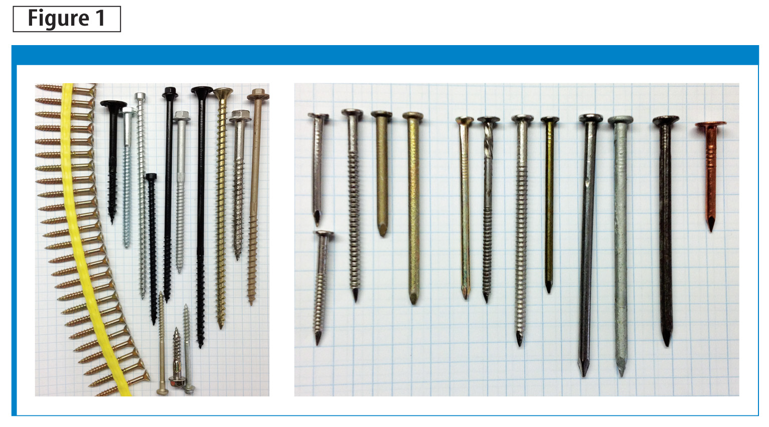
Small-diameter nails and screws (i.e. less than 6 mm [0.23 in.]) are vital to the performance of wood-frame construction. These fasteners (Figure 1) play a crucial role in:
- vertical and lateral load paths;
- hazard energy dissipation;
- fire safety;
- building serviceability;
- construction; and
- deconstruction of light-frame wood buildings.
The National Building Code of Canada (NBC) provides prescriptive guidance for fastening typical wood-frame construction. At the same time, the Canadian Standards Association (CSA) O86-09, Engineering Design in Wood, provides rational mechanics-based analysis methods for engineered design. Both of these resources rely on CSA B111, Wire Nails, Spikes, and Staples, as the reference specification for small-diameter driven fasteners. That standard was first approved in 1974, and although it was reaffirmed as recently as 2003, it was not updated. As a result, CSA B111 was a useful guide to driven fasteners but it did not reflect the many changes occurring since the early 1970s. These include the general use of power-nailers and fasteners designed to be installed with them, modifications in chemical wood treatments, corrosive conditions associated with those chemicals, and corrosion-resistant coatings. Now, CSA B111 has been withdrawn, leaving NBC and CSA O86-09 without a reference standard for nails.
In CSA O86-09, screws for wood construction are specified following American Society of Mechanical Engineers (ASME) B18.6.1, Wood Screws (Inch Series), and ASME B18.2.1, Square, Hex, Heavy Hex, and Askew Head Bolts and Hex, Heavy Hex, Hex Flange, Lobed Head, and Lag Screws (Inch Series). These standards are current, having been periodically reaffirmed. Many proprietary wood screws are now available that are more efficient than standard wood and lag screws. However, proprietary screws do not necessarily comply with ASME standards.
Fastener standards and the products themselves have been changing, as well as the corrosion environment and wood materials. Engineered wood products (EWP), such as structural composite lumber (SCL), wood structural panels (WSP), and wood I-joists are typical of contemporary light-frame construction. Fastening for these materials requires attention to the fundamentals to ensure connections perform as designed. A vital issue is the use of correct specific gravity (i.e. relative density) in connection design with EWP.
Finally, formulations for wood treatment chemicals to prevent decay have undergone major changes in the last decade. The changes were driven by recognized human toxicity of certain formulations and regulatory threats. New and common wood treatment chemicals result in a more corrosive environment for metal fasteners than earlier treatment chemicals. Heavy galvanization, galvanization in combination with barrier coatings, and stainless steel are solutions to corrosion resistance, but correct fastener specification is important to meet performance requirements.
This article aims to provide a recommendation for the withdrawn CSA B111, recognize proprietary wood screws, and elevate the importance of relative density and corrosion resistance during design and fastener specification.


Small diameter connection design
An overview of the codes and reference standards, NBC and CSA O86-09, for small-diameter fastening is shown in Figure 2. The NBC tables provide guidance for prescriptive fastening requirements while CSA O86-09 sections outline the analyses for engineered wood design.
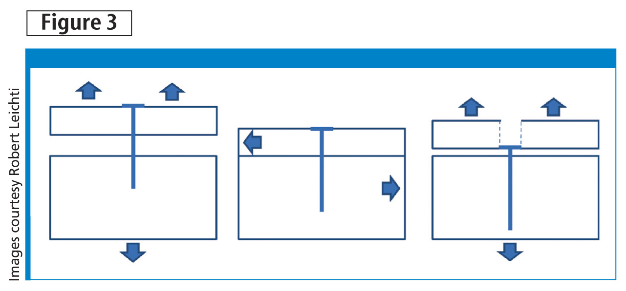
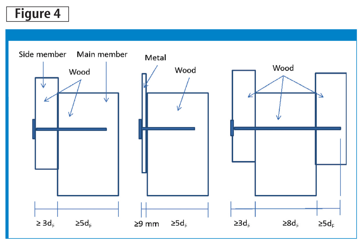
Typical connection design for small-diameter fasteners includes analysis for withdrawal resistance, lateral (shear) resistance, and head-pull-through for some nails and screws (Figure 3). The NBC prescriptive fastening schedules are based on unstated requirements found in details of applicable CSA O86-09 sections (Figure 4). For example, the calculated properties and prescriptive fastening schedules assume:
- connection members are in contact with each other;
- fasteners penetrate perpendicular to the face and are embedded in the side grain of both connection members;
- for wood–to-wood and steel-to-wood connections, minimum nail penetration in the main member is more than five times the fastener diameter1;
- screw penetration has the same requirements as nails2; and
- laterally loaded lag screws have a minimum penetration that is five times the diameter.3

Other requirements can be found in the applicable sections of NBC and CSA O86-09.
Engineering analysis of laterally loaded connections requires the design professional to solve a set of equations generally referred to as ‘yield limit equations,’ related to different yield mechanisms. The controlling mechanism might be yielding of the wood or rigid rotation of the fastener, or bending of the fastener with some wood crushing. The equations are based on engineering mechanics and variables include:
- embedding strength of the connection members based on their relative density;
- embedment length of the fastener in each connection member;
- fastener diameter; and
- bending yield strength of the fastener.
The equation producing the lowest numerical result controls design and describes the expected yield mechanism.
Nail specification
In NBC, Table 9.23.3.4 identifies typical framing connections and appropriate nails. The nails are defined in CSA B111, which as mentioned, is now withdrawn. CSA O86-09 identifies the same nails in Annex A.10.9.5.2, again with reference to CSA B111. A solution to the nail specification standard is available in ASTM F1667, Standard Specification for Driven Fasteners: Nails, Spikes, and Staples. This standard was introduced in 1998, was updated in 2011 following ASTM requirements, and is under the jurisdiction of ASTM Subcommittee F16.05.
ASTM F1667 provides specification requirements for driven nails, staples, and spikes, including:
- dimensional tolerances;
- physical properties;
- mechanical properties;
- materials;
- coatings for corrosion resistance;
- packaging; and
- workmanship.
Revealed in the standard scope statement, ASTM F1667 includes power- or hammer-driven fasteners. It also includes 59 tables of nails, staples, and spikes, not all of which are for structural fastening. The most important ASTM F1667 table, for use with NBC and CSA O86-09, is Table 15, Common Nails, and Table S1.1, Low and Medium Carbon Nails and Spikes, which shows the bending yield strength for nails.
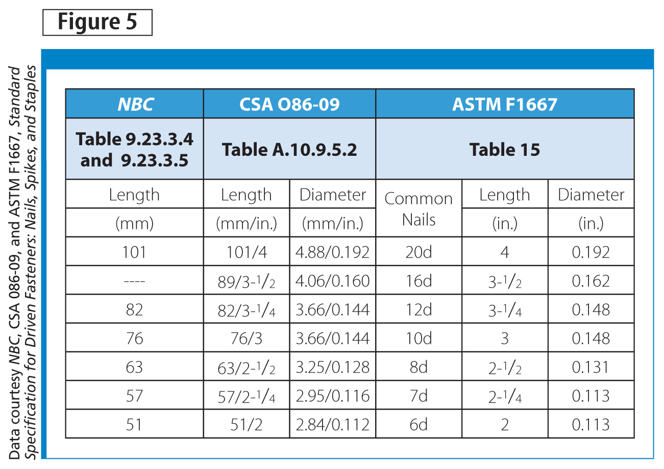
The nails specified in NBC and listed in the Annex of CSA O86-09 are shown in the first three columns of Figure 5, this illustrates the nails called out in NBC framing tables are recognized in CSA O86-09. Figure 5 also shows selected common nails from ASTM F1667. When the nails from the ASTM table are compared to nails shown in the CSA O86-09 Annex, it is clear the common ASTM nails are the same size (diameter and length) as Canadian standard nails.
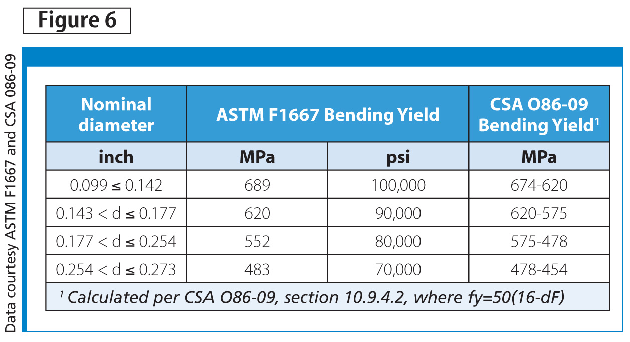
An important property of nails is the bending yield strength because it is critical to performance under lateral loads. In ASTM F1667, minimum average bending yield strength is specified for nails by diameter ranges. Figure 6 shows diameter ranges and the specified bending yield strengths. In CSA O86-09, the bending yield strength is a function of nail diameter where smaller diameter nails have greater bending yield strengths than larger ones. The bending yield strength, as calculated using the CSA O86-09 equation, are shown in Figure 6 for the range of nail diameters as laid out in ASTM F1667. A comparison of the ASTM F1667 specification for bending yield strength (third column) and the calculated requirement for CSA O86-09 nails (fourth column), shows the specification for bending yield strength in ASTM F1667 meets the requirements of CSA O86-09.
Nail specification includes some important considerations related to measurement of dimensions, tolerances, physical properties, mechanical properties, materials, coatings, workmanship, and packaging. CSA B111 offered specification related to basic dimensions and tolerances, but the information on materials and coatings were sparse. ASTM F1667 provides details on dimensions, tolerances, physical properties, mechanical properties, and materials. It also addresses coatings by calling out standard specifications depending on application and addresses workmanship and packaging.
Some nail manufacturers include ASTM F1667 compliance information on the product packaging, while some do not. However, the builder or design professional can request this information from the nail manufacturer so it can be included in construction documents.
In summary, the nails called out by length in NBC’s framing table are fully defined in the CSA O86-09 Annex. These nails can be specified as the common nails in ASTM F1667, Table 15.
Nail installation
Often in construction documents and jobsite discussions, nails are referred to by historical pennyweight nomenclature. In earlier times, pennyweight nomenclature referred to the cost in cents (i.e. pennies) for 100 nails of a given size. This terminology worked because variations in nail sizes were limited. Therefore, a ‘16d’ or ‘16-penny’ nail was well defined.
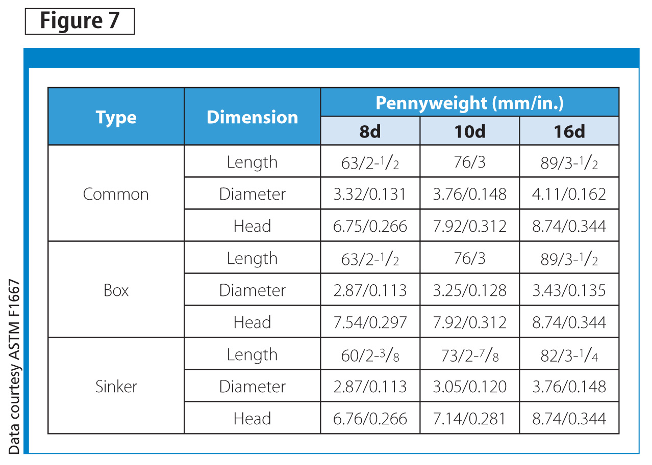
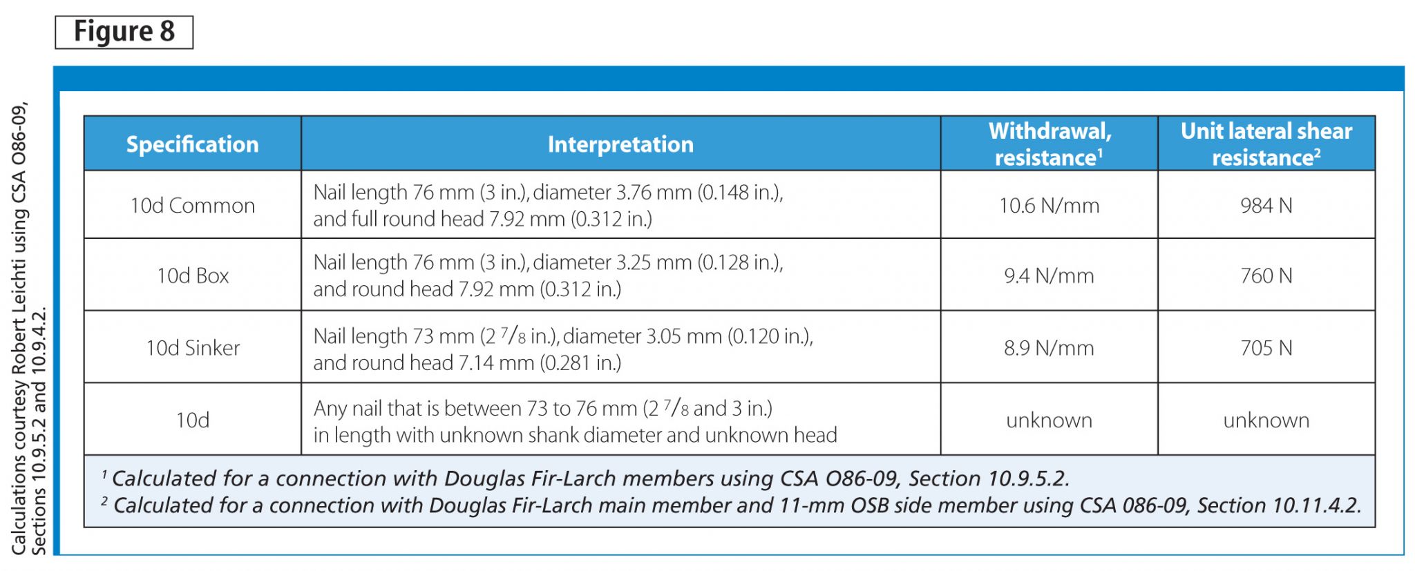
The problem with this in contemporary fastening is it only conveys information about length. Now, we have many common-length nails that differ in diameter, head geometry, or both. The issue is illustrated in Figure 7 where dimensions for common, box, and sinker nails are defined by pennyweight. Clearly, a 10d common nail is substantially larger than a 10d sinker in both diameter and length. When specifying nails, it is recommended diameter and length are given to prevent misinterpretation of the specified nail’s actual dimensions. An example is shown in Figure 8.
Figure 8 shows the outcome of complete specification with respect to withdrawal and lateral resistance properties. The 10d common specification has 19 per cent more withdrawal resistance than the 10d sinker and 39 per cent greater shear resistance. However, of concern is the ‘10d’ specification for which the withdrawal and lateral resistances are unknown because the diameter is unknown. (The ‘10d’ specification tells the user only the approximate length. It does not identify the diameter unless accompanied by the ‘common,’ ‘sinker,’ or ‘box.’) The complete specification by length and diameter is needed to build the designed performance.
Power-driven versus hand-driven nails
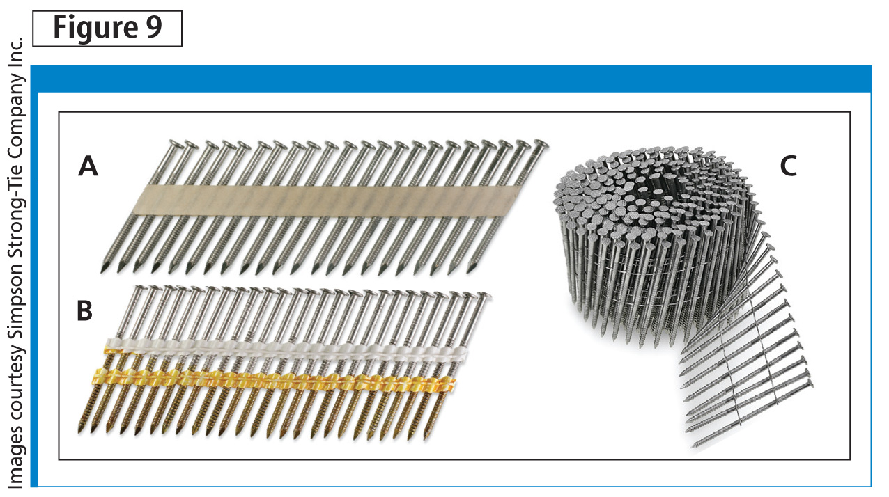
CSA B111 addressed only hand-driven nails, but ASTM F1667’s scope includes hand-driven and power-driven nails and staples. Power-driven (Figure 9) and hand-driven nails are both made from the same steel wire. As a result, hand-driven and power-driven nails of the same specification have equal:
- bending yield strengths;
- shank and length tolerances; and
- corrosion resistance requirements.
An exception to the similarity between power-driven and hand-driven nails may be in metal connector nails, which are usually hardened or tip-hardened in the former, but not the latter. This is because hand-driven nails are easily installed in punched holes, whereas power-driven nails are intended to penetrate the metal connector surface if the installer misses the punched hole. There may be some differences between hand-driven nails and power-driven nails in head geometry and head tolerances because of collation and tool requirements. Otherwise, the main difference between hand-driven and power-driven nails of the same size is the former is driven by a hammer or palm-nailer and the latter are collated for use in a power-nailer or stapler tool.
When nails are driven by hammering, over-driving nails is not a problem. With the use of power-nailers, over-driving can be an issue. Building officials have correctly rejected some constructions where nail placement was careless or nail penetration into the side member was excessive, whether the side member was a steel plate or a wood sheathing panel. Nails should be driven so their heads contact the side member surface, but not so deep the nail head’s top is below the plane surface of the side member. With metal hardware, nails should be driven through the pre-manufactured holes, and when nailing sheathing, attention to spacing and embedment in the framing is critical.
Wood and lag screws
Wood and lag screws are made from low carbon steel wire similar to wire used for nails. Most of the screw products available for wood construction are made by cold-forming the head and roll-forming the threads, and most screws are case hardened so they are durable enough to drive. Even though case hardening increases bending yield strength and improves drive performance, it can make the screw more brittle. Corrosion resistance for small-diameter screws is usually by mechanical galvanization with a passivation top coat and/or barrier coating.
ASME B18.6.1 and ASME B18.2.1 identify and provide dimensions and tolerances for specific thread patterns, thread lengths, head geometries, tips, drive recesses, and materials. Some screws meet those specific features and are in compliance with the standards. While many proprietary screws do not meet geometric criteria of ASME standards by design, they are also intended to be used in specific applications and may provide better capacity and easier drive than ASME standard screws. It is important to note ASME standards for screws only define the screw or lag screw’s physical characteristics, but the standards do not offer specific engineering performance in terms of withdrawal resistance, lateral resistance, or pull-through resistance.
NBC permits the use of wood screws in wood frame construction. In NBC Table 9.23.3.5, wood screws are included for fastening subfloor. However, no other guidance is offered by NBC on the use of screws in Section 23, Wood-frame Construction. Of course, screws can be used for other applications, and should be qualified for those uses.
Some applications requiring qualified screws or systems are:
- metal connector and metal roofing fastening;
- wood structural panel fastening for shear walls and braced walls;
- sheathing fastening for diaphragms other than subfloor; and
- substitution for lag screws in applications, such as ledger attachment or sole plate-to-rim or joist connections.
Proprietary screws used for qualified applications will have engineering properties based on testing and analysis.
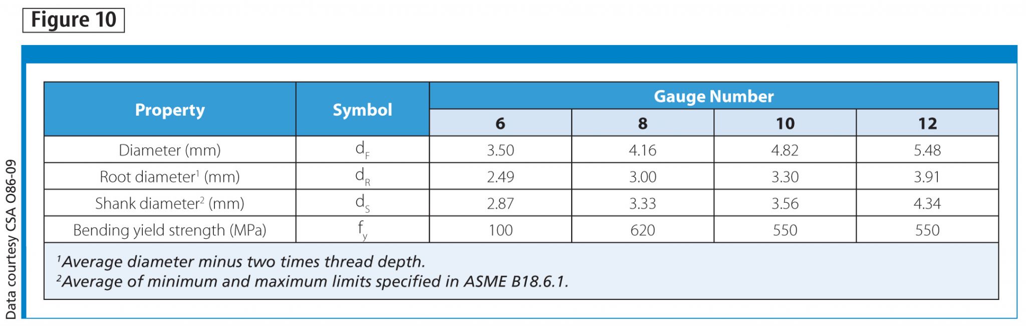
Wood screws are addressed in CSA O86-09, section 10.11. The section provides the nominal diameter of the threaded shank for four typical standard wood screws, and also identifies the required minimum bending yield strength for those sizes. Table information is incomplete in that it only offers the fastener’s major diameter as measured over the threads, and bending yield strength, which are needed for calculation of lateral resistance. However, other dimensions, root diameter (dR) and shank diameter (dS) may be needed to calculate lead hole requirements. Figure 10 reproduces the CSA O86-09, Table 10.11.1 information for fastener diameter and bending yield strength, and also includes the root and shank diameters for ASME wood screws.
The installation of wood screws into a wood with relative density greater than 0.50, requires a pre-drilled hole. The requirements for pre-drilled hole sizes are given in CSA O86-09, Table 10.11.2. The hole’s size is a function of the root diameter or shank diameter, depending on the relative density.
Lag screws also are to be installed in pre-drilled holes. Holes for lag screws are two steps (CSA O86-09, section 10.6.2.1)—that is, the first part of the hole is drilled for the unthreaded shank, and the second part is drilled to a specific proportion of the threaded shank, depending on the wood species.
Self-drilling screws may not be in compliance with ASME standards for wood screws and lag screws because of certain geometric features. However, they can be installed following the manufacturer’s instructions and achieve specific engineered performance. The main reason for using the self-drilling screws is they do not require pre-drilled holes and engineering performance is available from the manufacturer.
Specific gravity or relative density
Specific gravity is the relative density of a material in comparison to the density of an equivalent volume of water. As a result, specific gravity is sometimes called ‘relative density.’ The relative density of wood-based materials is a function of moisture content because the volume of wood-based materials changes with moisture content due to shrinkage and swelling. For this reason, CSA O86-09 standardizes the mean relative density to an oven-dry moisture basis (zero moisture). The mean relative densities for visually-graded Canadian lumber species combinations are given in CSA O86-09, Table A.10.1.
This is important to fastener engineering because the relative densities of connection members play a significant role in the fastener’s performance, which affects the load capacity and load deformation characteristics of the connection. Calculated lateral resistance and withdrawal depend on relative density. With sawn lumber, the relative density to use in calculations is the assigned mean relative density for the wood species or species combination as given in CSA O86-09. However, engineered wood materials may require an equivalent value and not the physical relative density.
Engineered wood products, such as structural composite lumber and wood structural panels, are used as framing members and for flanges of wood I-joists and rim boards. When designing connections including these products, the assigned equivalent relative density should be used. The actual relative density and assigned equivalent relative density may not be equal. Further, like sawn lumber, EWPs have directional mechanical properties, and while mean relative density is not a directional property, the equivalent relative density for fastening may be directional and depend on the fastener type. The equivalent specific gravity property is developed by following the procedure of ASTM D5456, Standard Specification for Evaluation of Structural Composite Lumber Products, Annex A2, which outlines test and analysis methods to establish an equivalent property based on the performance of a standard fastener in the subject material.
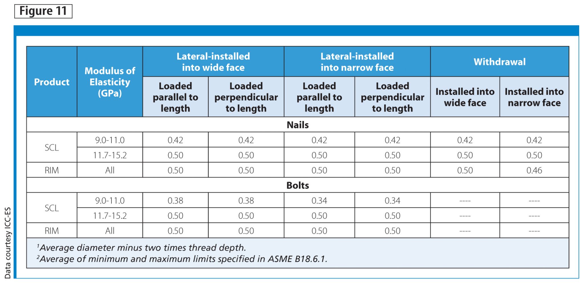
Engineered wood products are proprietary products and have engineering reports describing their unique engineering properties. Figure 11 shows elements of the equivalent specific gravity table from an evaluation report for an SCL product line. The table shows for these products, the equivalent specific gravity is a function of:
- grade;
- fastener orientation;
- direction of loading relative to the grain;
- character of load (withdrawal or lateral); and
- fastener diameter.
The equivalent specific gravity properties are available in product literature and evaluation reports for engineered wood products.
Fastener corrosion resistance
NBC and CSA O86-09 have requirements for protection from decay. These appear in NBC section 9.23.2.2 and CSA O86-09, section 4.3.4.2. The American Wood Protection Association (AWPA) provides guidance on treatment chemicals and retention and penetration requirements for various applications. While there are requirements for decay prevention, there is no corrosion resistance specification in the NBC or CSA 086-09 design guidelines. U.S. building codes addressed the issue by using hot-dip galvanized per ASTM A153, Standard Specification for Zinc Coating (Hot-Dip) on Iron and Steel Hardware, Class D, as the benchmark performance for nails and fasteners used in contact with chemically treated wood. As an alternative to hot-dip galvanization, those codes permit corrosion resistance mechanisms by the base metal.
Examples of corrosion-resistant base metal choices could be copper, silicon bronze, or stainless steel. In the United States, the International Residential Code (IRC) also permits mechanical galvanization per ASTM B695, Standard Specification for Coatings of Zinc Mechanically Deposited on Iron and Steel, Class 55, for screws as an exception to the hot-dip galvanization requirement.
Several strategies can be used to evaluate fasteners’ corrosion resistance. A frequent choice is salt-spray testing following ASTM B117, Standard Practice for Operating Salt Spray (Fog) Apparatus. The result of this test is a number of hours until a specific corrosion condition develops. An issue with salt-spray testing is the direct correlation to natural environments is not assured.
For fasteners in contact with chemically treated wood, ASTM G198, Standard Test Method for Determining the Relative Corrosion Performance of Driven Fasteners in Contact with Treated Wood, can be used to establish a comparative corrosion resistance. This test method calls for fasteners to be embedded in chemically treated wood and then placed in a high moisture environment for predetermined exposure duration. After the exposure period, fasteners are removed from the wood member and the relative corrosion of the benchmark fastener and the specified fastener are compared.
The International Code Council Evaluation Service (ICC-ES) uses Acceptance Criteria (AC) 257 to assess corrosion resistance of coated fasteners embedded in chemically treated wood. The method of ICC-ES AC257 is a side-by-side test strategy with hot-dip galvanized fasteners embedded in the same material as the alternate fastener. For an ICC-ES AC257 evaluation report, the proponent decides one of the four exposure conditions to be recognized, and then has the alternate fasteners tested following the specified protocols. (This process has not been adopted in Canada, but the qualification of corrosion resistance is appropriate.)
For the General Use category, which is use with treated wood in high moisture, fasteners are embedded in chemically treated wood, and then exposed for 1500 hours in continuous non-salt water fog and cyclic fog-dry environments. For the Unrestricted Use category, the same tests are conducted using salt fog. To pass the performance test, the proponent fastener must show corrosion resistance that meets or exceeds the corrosion resistance of the benchmark hot-dip galvanized fasteners.
Stainless steel
Corrosion resistance can be achieved by using a fastener with a corrosion resistant base metal. CSA B111, CSA O86-09, and NBC do not address stainless steel. The International Building Code (IBC) and the IRC permit the use of stainless steel for fasteners in contact with chemically treated wood or in corrosive environments. In Section 6 of ASTM F1667, four types of stainless steel are identified for nails and staples: Types 302, 304, 305, and 316. These differ in basic alloy content, are all austenitic grades, are inherently non-magnetic, and cannot be hardened by heat treatment.
At the same time, the differences in alloy formulation create differences in corrosion resistance. Of the four types listed in the standard, Type 302 offers the lowest level of corrosion resistance, although superior to carbon steel, while 304 and 305 have similar corrosion resistance better than that of Type 302. Type 316 has the best corrosion resistance, especially in environments with chlorides.
Screws are sometimes made with Type 410 stainless steel. This is martensitic, magnetic steel that can be heat-treated to increase hardness. It is adequate for use in mildly corrosive environments, but is not appropriate for moderately or severely corrosive environments.
Conclusion
Fasteners in light-frame construction play an important role in the building system’s performance. This review of available standards and important considerations to light-frame fastening can be summarized in the following points:
- ASTM F1667 specification for driven fasteners can be used as an alternate to the withdrawn CSA B111 standard for nails;
- nail specification is complete by calling out length and diameter, which prevents misinterpretation of nail size and casual substitution;
- power-driven and hand-driven nails have the same requirements in terms of bending yield strength, ductility, corrosion resistance, and dimensions—over-driving nails with power-nailing tools should be avoided;
- ASME standards outline geometry and other important physical characteristics of wood and lag screws, but do not provide engineering properties and proprietary wood screws offer enhanced performance relative to standardized wood screws and lag screws;
- mean relative density for sawn lumber is given in CSA O86-09, and equivalent relative density for EWPs is available from the product manufacturers;
- fastener design requires the correct mean relative density for sawn lumber or the correct equivalent specific gravity for EWPs;
- wood treatment chemicals create a highly corrosive environment for low-carbon-steel fasteners, and fastener corrosion resistance should be part of the fastener specification for any application that involves wood treatment chemicals or a corrosive natural environment; and
- stainless steels are not all the same with respect to corrosion resistance—fasteners made from Type 316 provide the highest corrosion resistance.
Notes
1 For more, see CSA O86-09, Figure 10.9.2.2. (back to top)
2 For more, see CSA O86-09, Section 10.11.2.3. (back to top)
3 For more, see CSA O86-09, Section 10.6.3.3. (back to top)
 Robert Leichti is fastening systems engineering manager at Simpson Strong-Tie Company Inc., located in Pleasanton, California. He was a professor of wood and fibre engineering at Oregon State University in the Department of Wood Science and Engineering for 19 years and has spent 12 years of research and development and compliance and product engineering in the building materials and hand tools industries. Leichti is actively involved with standards development through ASTM and International Organization for Standardization (ISO) and is a regular participant in the criteria development process for the evaluation of alternate building materials. He can be contacted by e-mail at rleichti@strongtie.com.
Sign up for our weekly newsletter
Construction Canada weekly newsletters give the latest AEC industry news for those who build, design, engineer, specify, renovate or operate in the built environment.
Products & Services


Read the Latest Issue
